Hubble Servicing Mission SM4
Status Report #4
The ESA engineering support activities during the SM4 mission are basically split into two different parts, covered by the "planning shift" and the "orbit shift", with a duration of 12 hours each and with the planning shift lasting from 3 PM to 3 AM.
 |
|
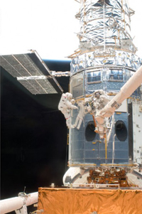
The ESA hardware maintains the solar pointing aspect of the arrays. Credit: NASA |
Apart from the direct monitoring of the mission progress, potential upcoming issues are to discussed on-line with our NASA interface colleagues in order to assure that no activities will be carried out during the mission, which could jeopardize the ESA-provided hardware or which might pose any risk to the hardware itself and subsequently to the mission.
The planning shift for 15 May
During the planning shift on May 15 the following activities were performed:
The HST ESA planning shift team followed all activities linked to EVA-2 operations, planning, handling and slewing of the Solar Array and monitored available Solar Array Drive and Electronics (SADE) housekeeping data. Between 20:00 and 23:00 GMT, two Solar Array slews were performed from 0 to 90 deg and back to 0 deg to charge the new set of batteries and to check that they function correctly.
 |
|
This image clearly demonstrates the importance of suitably aligning the solar arrays during EVAs. Credit: NASA |
A typical example for an activity checked closely during the planning shift was the investigation of a potential inadvertent Solar Array angular slippage during Airlock Depress activities prior to EVA activities – this could occur as a result of the associated airflow acting on the Solar Array. Flight rules require that during Airlock Depress activities, the Solar Array is monitored by a camera to allow for quick intervention in case of excessive inadvertent solar array rotation. NASA discussed using the camera for purposes other than for Solar Array slew monitoring; this would require a deviation from flight rules.
Though analysis showed that with the intended configuration inadvertent slewing during Airlock Depress is unlikely, it was recommended by ESA not to change the flight rules and to go for the procedure as originally planned.
Another typical planning investigation performed was based on a NASA request to monitor and document micro-meteorite damages on the Solar Array wings. Solar Array slewing outside its typical operational range had been suggested in order to provide an adequate view by the on-board camera. Together with the NASA Computer Aided Design (CAD) team, a configuration was found which allows monitoring of the relevant wing impact area by two cameras and remaining within the mission typical solar array slew angle.
Prepared by Michael Eiden, 18 May 2009
Editor's note: The ESA HST team provides engineering support for the ESA hardware on the HST: the two Solar Array Drive Mechanisms (SADM), the Solar Array Drive Electronics (SADE), and the Drive Control Electronics (DCE).
The team comprises Michael Eiden (ESA HST Project Manager) and Lothar Gerlach from the technical directorate at ESA, and Udo Rapp and Manfred Schmid from EADS Astrium.
