Instruments
Overview
Observing gamma rays is a difficult task. The gamma-ray photons from distant objects are rare and with their penetrating power they cannot be focused by conventional mirrors or lenses. It requires specially designed detectors to register the gamma rays from space and determine their position of origin on the sky.
INTEGRAL has two such detectors on board: an Imager and a Spectrometer. Two monitor instruments support these instruments: an X-ray monitor and an optical camera. All four instruments are co-aligned and observe the same region of the sky simultaneously. This allows scientists to clearly identify gamma-ray sources, a key feature in studying high-energy processes in the violent Universe.
All instruments are provided by large collaborations encompassing many scientific institutes in the ESA member states, United States, Russia, Czech Republic, and Poland. Principal investigators in different European countries lead the nationally funded collaborations.
SPI
|
Principal investigators |
|
|
J.-P. Roques |
J. Greiner |
 |
|
SPI |
The spectrometer SPI (Spectrometer on INTEGRAL) measures gamma-ray energies with exceptional precision. It is 100 times more sensitive than the previous high spectral-resolution space instruments. SPI performs spectral analysis of gamma-ray point sources and extended regions over an energy range between 18 keV and 8 MeV with an unprecedented energy resolution of 2.2 keV (FWHM) at 1.33 MeV.
This is accomplished using an array of 19 hexagonal high purity germanium detectors cooled by a Stirling cooler system to an operating temperature of -188 °C (85 K). It makes the Spectrometer extremely heavy with a mass of 1300 kilograms.
 |
|
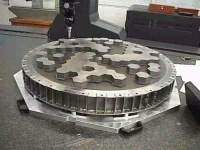
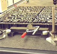
SPI Mask |
The total detection area is 500 square centimetres. A hexagonal coded aperture mask is located 1.7 m above the detection plane in order to image large regions of the sky (fully coded field of view = 16 degrees) with an angular resolution of 2 degrees. It is made of 3 centimetre thick tungsten and consists of 127 hexagonal elements, of which 63 are opaque, 64 transparent. The construction allows the imaging of large regions of the sky.
 |
|
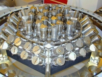
SPI Veto System |
To reduce the background radiation, the detectors are shielded by bismuth germanate oxide crystals, these act as a veto (anticoincidence) system and extend around the bottom and side of the detector almost completely up to the coded mask. The aperture (and hence contribution by cosmic diffuse radiation) is limited to ~ 30°. A plastic veto is provided below the mask to further reduce the 511 keV background.
Table Showing Predicted Performance
Parameter |
Value |
| Energy range | 18 keV - 8 MeV |
| Detector area | 500 cm2 |
| Spectral resolution (E/ΔE @ 1 MeV) |
~ 450 (i.e. 2.33 keV FWHM @ 1.33 MeV) |
| Field of view (fully coded) | 14° flat-to-flat 16° corner-to-corner |
| Zero Coding | 32° flat-to-flat 35° corner-to-corner |
| Angular resolution (point sources) | 2.5° FWHM |
| Point Source Positioning | <1.3° |
| Narrow-line sensitivity - 3σ in 106 s, @ 1 MeV - 3σ in 106 s, @ 511 keV |
2.4 x 10⁻⁵ phs-1cm-2 4.6 x 10⁻⁵ phs-1cm-2 |
| Continuum sensitivity (3σ in 106 s, @ 1 MeV) |
8.8 x 10⁻⁴ phs-1cm-2MeV-1 |
| Timing accuracy (3σ) | 0.129 ms |
| Resources (following EID-A allocation) | |
| Mass | 1309 kg |
| Power (sun/eclipse) | 385/110 W |
| Data rate | 45 kps |
IBIS
|
Principal investigators |
||
|
P. Ubertini |
F. Lebrun |
G. DiCocco |
 |
|
IBIS Detector and Mask |
The imager on-board INTEGRAL (IBIS) is giving sharper gamma-ray images than any previous instrument. IBIS provides diagnostic capabilities of fine imaging (12 arcmin FWHM), source identification and spectral sensitivity to both continuum and broad lines over a broad (15 keV - 10 MeV) energy range. The imager examines, simultanesously with the other instruments on INTEGRAL, celestial objects of all classes ranging from the most compact galactic systems to extragalactic objects. A tungsten coded-aperture mask (located at 3.2 m above the detection plane) is optimised for high angular resolution.
As diffraction is negligible at gamma-ray wavelengths, the angular resolution obtainable with a coded mask telescope is limited by the spatial resolution of the detector array. The spatial resolution is dependent on the number of small sensitive elements of the detector, called pixels (picture elements). IBIS has a detector with a large number of pixels, all physically distinct from one another.
|
|
|
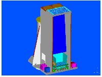
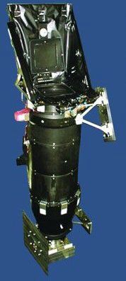
IBIS Instrument |
The detector uses two parallel planes of pixels located one on top of the other and separated by 90 mm. The top layer (ISGRI) is made of 16 384 cadmium telluride (CdTe) pixels, covering 2600 square centimetres and each measuring 4x4x2 millimetres. This layer detects the low-energy gamma rays. The second layer (PICsIT) consists of 4096 caesium iodide (CsI) pixels, each 9x9x30 millimetres covering 3100 square centimetres. This layer captures high-energy gamma rays.
The division into two layers allows scientists to track the paths of the photons in 3D, as they scatter and interact with more than one element.
 |
|
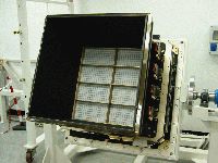
IBIS Coded Mask |
Events can be categorised and the signal to noise ratio improved by rejecting those which are unlikely to correspond to real (celestial) photons, for example towards the high end of the energy range. The aperture is restricted by a lead shielding tube and shielded in all other directions by an active bismuth germanate oxide (BGO) scintillator veto system.
IBIS was put together by a number of collaborating institutes from around the world:
-
Italy (IAS Rome, ITESRE Bologna, IFCAI Palermo)
-
France (CEA Saclay)
-
Norway (U Bergen)
-
Germany (U Tuebingen)
-
Spain (U Valencia)
-
USA (NASA/MSFC Huntsville)
-
Poland (Space Research Centre, Warsaw)
-
UK (U Southampton)
Table Showing Predicted Performance
Parameter |
Value |
| Energy range | 15 keV - 10 MeV |
| Detector area | 2600 cm2 (CdTe) 3100 cm2 (CsI) |
| Spectral resolution | 8% @ 100 keV 10% @ 1 MeV |
| Field of view | 8.3° x 8.0° fully coded 29.1° x 29.4° zero response |
| Angular resolution | 12 arcmin FWHM |
| Point Source Location Accuracy | 30'' @ 100 keV - 50σ source 3'' @ 100 keV - 5σ source 5-10'' @ 1 MeV - 5σ source |
|
Narrow-line sensitivity |
1.9 x 10⁻⁵ phs-1cm-2 3.8 x 10⁻⁴ phs-1cm-2 |
| Continuum sensitivity - 3σ in 105 s, @ 100 keV, ∆E = E/2 - 3σ in 105 s, @ 1 MeV, ∆E = E/2 |
|
| Timing accuracy (3σ ) | 61 μs |
|
Typical Source Location |
|
| Resources (following EID-A allocation) | |
| Mass | 677 kg (+96 kg for tube) |
| Power (sun/eclipse) | 240/0 W |
| Data rate (solar maximum) | 59.8 kbit/s |
| Date rate (solar minimum) | 56.8 kbit/s |
JEM-X
|
Principal Investigator |
|
Søren Brandt |
The Joint European X-Ray Monitor (JEM-X) is one of four instruments on ESA's INTEGRAL mission. It plays a crucial role in the detection and identification of the gamma-ray sources. JEM-X makes observations simultaneously with the main gamma-ray instruments and provides images in the 3 - 35 keV prime energy band with an angular resolution of 3 arcmin. It consists of two identical instruments and, like IBIS and SPI, uses the coded-mask technique for imaging. Two coded masks are located 3.2 metres above the detection plane.
 |
|
JEM-X Instrument |
The detector, an imaging micro strip gas counter, consists of two identical high pressure gas chambers filled with a mixture of xenon and methane at a pressure of 1.5 bar, that is 1.5 times the normal atmospheric pressure at sea level. When an incoming X-ray hits the xenon gas it knocks off an electron which is accelerated by the electric field in the detector and knocks off even more electrons. The electrons cascade onto one of the wires in the detector. By measuring the size of the electric charge on the wire scientists can determine the energy of the initial X-ray. JEM-X contains crossed wires so scientists can also determine the location of the electron cascade representing the incoming photon. The total detection area of JEM-X is 1000 square centimetres.
JEM-X has been built by a number of collaborating scientific institutes in Denmark (DSRI Lyngby), Finland (Metorex Espoo, U Helsinki), Spain (U Valencia, INTA Madrid), Italy (IAS Frascati, U Ferrara, IFCAI Palermo, ITESRE Bologna), USA (NASA/GSFC Greenbelt), Sweden (Observatory Stockholm), United Kingdom (U Cambridge), Poland (Copernicus Center Warsaw, Space Research Center Warsaw), Russia (IKI Moscow).
Table Showing Predicted Performance
Parameter |
Value |
| Energy range | 3 - 35 keV |
| Detector area | 2 units, 500 cm2 each |
| Spectral resolution | 1.3 keV @ 10 keV |
| Field of view | 4.8° fully coded 7.5° half response 13.2° zero response |
| Angular resolution | 3 arcmin FWHM |
| Point Source Location Accuracy | 1' (90% confidence, 15σ isolated source) |
|
Narrow-line sensitivity |
1.64 x 10⁻⁴ phs-1cm-2 1.30 x 10⁻⁴ phs-1cm-2 |
| Continuum sensitivity - 3σ in 105 s, @ 6 keV - 3σ in 105 s, @ 30 keV |
1.2 x 10⁻⁴ phs-1cm-2keV-1 1.0 x 10⁻⁴ phs-1cm-2keV-1 |
| Timing accuracy (3σ ) | 122 µs (relative) 1 ms (absolute) |
| Typical Source Location (10σ source) | < 30" |
| Resources (following EID-A allocation) | |
| Mass | 65 kg |
| Power (sun/eclipse) | 50/0 W |
| Data rate (solar maximum) | 7.0 kbit/s |
| Date rate (solar minimum) | 7.0 kbit/s |
OMC
|
Principal Investigator |
|
Miguel Mas-Hesse |
 |
|
The OMC |
The optical camera on-board INTEGRAL offers the first opportunity to make long observations of the visible light coming from gamma-ray and X-ray sources. Multiwavelength observations are particularly important in high-energy astrophysics where variability is typically rapid. Using wide-band observation, INTEGRAL provides simultaneous observations over seven orders of magnitude in photon energy for some of the most energetic objects in the Universe for the first time.
The optical monitoring camera OMC is placed on top of the satellite and is sensitive to stars with a visual magnitude up to 19.7. The OMC is a standard optical refractor with a 5-centimetre lens and a CCD (charge-coupled device, 2055 × 1056 pixels, imaging area: 1024 × 1024 pixels) in the focal plane. The CCD is located in the focal plane of a 50 mm (diameter) lens including a Johnson V-filter to cover the 500 - 600 nm wavelength range. These silicon chips consist of pixels (picture elements), which convert impinging photons into an electric charge. The accumulated charge is transferred out of the device and recorded. The data can then be converted into an image. To reduce noise, the CCD head of the OMC is cooled to -80 °C.
The instrument has been built by collaborating scientific institutes in Spain (INTA/LAEFF Madrid, U Valencia, U Barcelona), Ireland (UC Dublin), Belgium (U Liege), United Kingdom (MSSL Dorking), Czech Republic (Astroph. Institute).
Parameter |
Value |
| Field of view | 4.979° × 4.979° |
| Aperture | 5 cm diameter |
| Focal length | 153.7 mm (f/3.1) |
| Optical throughput | > 70% at 550 nm |
| Stray light reduc. factor* (within UFOV^) | << 1e-4 (no stray light detected) |
| Detector | 50 mm lens + CCD (2055 × 1056 pixels) imaging area = 1024 × 1024 pixels |
| Pixel size | (13 × 13) μm² = (17.5 × 17.5) arcsec² |
| CCD Quantum efficiency | 88% at 550 nm |
| CCD full well capacity | ~120 000 electrons/pixel |
| Angular resolution | ~23" Gauss PSF (FWHM=1.3±0.1 pix) |
| ADC levels | 12 bit signal, 4096 levels: ~30 cts/digital level (low gain) ~5 cts/digital level (high gain) |
| Frame transfer time | ≈2ms |
| Typical integration times | 10s - 50s - 200s |
| Time resolution | >3s |
| Limiting magnitude | 18.1 [V, 10×200s, 3σ] 18.9 [V, 50×200s, 3σ] 19.3 [V, 100×200s, 3σ] |
| Photometric accuracy | <0.3 mag for <16 mag and >300 s |
| Point source location accuracy | ~2" |
IREM
The INTEGRAL Radiation Environment Monitor (IREM) performs a wide range of radiation monitoring functions in-orbit, and downloads the results via the INTEGRAL spacecraft telemetry to the ground.
The IREM data are part of the spacecraft "housekeeping" stream and, as such, are made available to all users via the ISDC.
The design of the IREM is based on that of the Standard Radiation Environment Monitor (SREM), which is designed as a standard equipment compatible with all common spacecraft interfaces and mission constraints. The main difference between the IREM and other SREMs is the small interface box between the IREM instrument and the INTEGRAL spacecraft.
Coded Masks
The Imager, Spectrometer, and X-ray monitor share a common principle of operation: they are all coded-mask telescopes. Gamma-rays cannot be focalized with lenses or mirrors. To make an image of the gamma-ray sky, one is forced to use the coded mask technique. It consists to detect the shadow of a mask placed on top of the telescope and made of opaque and transparent elements. The gamma-rays project the shadow of the mask onto the detector plane.
Since there are many holes on the mask the gamma-rays coming from one source produce many overlapping images of the object. A coded mask, however, is designed so that each object in the field of view casts a unique shadow. A computer can decode the composite image and translate it into a scene of the gamma-ray source in the sky.
|
|
|
Different Contributions from Two Sources |
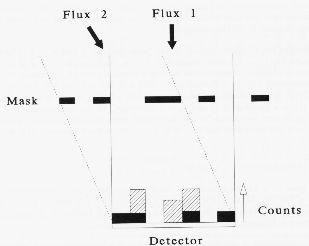
If there is only one source, the shift of the projected shadow with respect to the telescope axis allows determination of the direction of the source and thus its position on the sky. If there are more than one source, different shadows of the mask overlap. The detected pattern of light and shadow has then to be analysed in order to assess the observed image of the sky (finding the position and intensity of the different sources). This procedure is called the image deconvolution.
The coded mask technique has the advantage to allow an almost perfect removal of the background sky. The sides of the telescope are shielded to prevent the detection of photons which did not pass through the mask.
TIMM
The INTEGRAL Mass Model project (TIMM) aims to provide an independent and uniform instrument and spacecraft modelling program for ESA. The model is based on data received from the instrument teams about the mass distribution and chemical composition of material in their instrument. This information is collated, together with information about the spacecraft structure, to form a Monte Carlo model of the whole payload which can be used to provide the following benefits to the INTEGRAL project:
- Assessment of the relative performance of each instrument
- Assessment of the effect the payload has on a particular instrument
- Transferability of calibration results between instruments
- Uniform evaluation of event rates in detection elements
- Assessment of on-board s/w algorithms and telemetry requirements
- Assessment of off-axis shadows
- Assessment of degradation of the instrument response
- Assistance in post-launch trouble shooting
