Instruments
LISA Technology Package
The LTP represents one arm of a space-based gravitational wave interferometer, in which the distance between the two test masses is reduced from 5 million kilometres (in a 'LISA-like' mission concept) to 35 centimetres. The test masses fulfil a double role: they serve as mirrors for the interferometer and as inertial references for the drag-free control system. The main role of the LTP is to house the test masses and to provide the position information of the test masses to the Drag-Free and Attitude Control System (DFACS).
 |
|
|
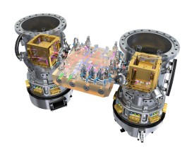
Illustration of the LISA Technology Package (left), and (right) its location in the LISA Pathfinder science module. Credit: ESA/ATG medialab |
|
The LTP DFACS consists of an inertial sensor, a proportional micro-propulsion system and a control loop. The inertial sensor subsystem is designed such that a cubic test mass located at the centre is free from all external forces except inertial gravity. The two identical test masses, each one a 46 mm cube composed of gold:platinum alloy, are housed in individual evacuated enclosures. The displacement of the cubes with respect to their housing is measured by capacitive sensing in three dimensions. These position signals are used in a feedback loop to command proportional micro-propulsion thrusters to enable the spacecraft to remain centred on the proof mass (see article on Drag-Free and Attitude Control System, for further details). Cold-gas thrusters (see article on Drag-Free Propulsion System, for further details) will be used as the micro-propulsion elements.
Although the proof masses are shielded from non-gravitational forces by the spacecraft, cosmic rays and solar flare particles can significantly charge them, leading to electrostatic forces that can corrupt the measurements by the inertial sensor. A charge management system comprising fibre-coupled UV lamps will discharge the test masses at regular intervals. As surface effects on the test masses can cause electrostatic forces, the test masses have to be coated very carefully to avoid contamination. In order not to damage the test masses during launch, a caging mechanism is used to maintain them in a safe and locked position during launch.
The caging mechanism design and implementation was particularly challenging. The mechanism is required to hold the mass while it is subjected to a very large force (2000 Newton) during launch, without damaging its surfaces. After launch, the test mass must be released at the correct position with high accuracy (60 µm) and with a release speed less than 5 µm per second (18 mm per hour!), in order to allow the electrostatic suspension system to take over the position control.
The test mass can also be disturbed by the presence of a very small amount of gas inside the enclosure. If the gas pressure were higher than 10-5 Pa, equivalent to the pressure of the near-Earth outer space, a combined effect of this residual pressure with small temperature unevenness would produce what is known as the radiometer effect, which would disturb the experiment. The vacuum enclosures therefore have to be designed and built with special getter pumps capable of maintaining the required vacuum for the duration of the mission.
Using two test masses, the reference point for the drag-free system can be chosen to be on either of the masses or at any point between them. Having two test masses also allows verification of the performance of the drag-free control loop by sensing the movement of the second mass relative to the spacecraft while the spacecraft follows the first test mass (see article on Drag-Free and Attitude Control System, for further details).
The position of the test masses, with respect to the spacecraft or each other, is measured by an interferometric system that is capable of picometre (10-12 m) precision in the frequency band 10-3 Hz to 10-1 Hz. The interferometric measurement system utilises a heterodyne Mach-Zehnder architecture, with all components rigidly bonded to an ultra-low expansion base-plate, manufactured from Zerodur.
The LISA Technology Package is the European-provided payload onboard LISA Pathfinder. The instrument is built by a consortium of European National Agencies and ESA. The subsystems have been integrated and tested under the control of Airbus Defense and Space GmbH (the LISA Pathfinder Architect). The fully integrated technology package has been integrated into the LISA Pathfinder spacecraft under the control of Airbus Defense and Space Ltd, the Industrial Prime Contractor.
Disturbance Reduction System
The Disturbance Reduction System (DRS) will validate system-level technologies required for use on 'drag-free' spacecraft, that is, spacecraft that are controlled to follow a trajectory determined only by external gravitational forces (a geodesic). The DRS eliminates other forces, such as solar radiation pressure, that would disturb the trajectory.
The DRS is a NASA-supplied system, which contributes to the LISA Pathfinder mission goals and uses the European LTP as a gravitational sensor. The DRS actuator consists of two clusters of colloidal thrusters that use ionised droplets of a colloidal solution accelerated in an electric field to provide micro-propulsion, and drag-free control software residing on a dedicated computer. The DRS will use the sensor information from the LTP (test mass positions and attitude) to control the spacecraft position and attitude.