Engineering
Structure
The spin-stabilised Ulysses spacecraft has a box-type structure with two overhanging balconies and a single aluminium honeycomb equipment platform. All electronics units of the scientific instruments and spacecraft subsystems, most of the sensors and the propellant tank are mounted on this platform. The Radio-isotope Thermoelectric Generator (RTG) which provides the spacecraft's main power is mounted on an outrigger structure to minimise its radiation effects and to isolate the main subsystems and the experiments from excess heat.
 |
|
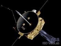
Artis's impression of Ulysses |
The electrical antennas of the URAP wave experiment consist of a pair of radially extending wire booms in the spin plane and an axial boom deployed along the orbital spin axis. The wire booms consist of 5 mm wide and 0.04 mm thick Cu-Be ribbon stowed during launch on two identical drive units. The wires were deployed to a length of 72.5 m tip-to-tip by centrifugal forces acting on tip masses after the second trajectory correction manoeuvre (TCM-2). Each wire boom has a passive tubular root damper which reduces relative motions between the boom and the spacecraft by natural material damping with a time constant of 3.5 h.
The axial boom element is formed by a pre-stressed, coilable elastic Cu-Be tube anchored in the axial-boom drive mechanism located on the rear face of the spacecraft. The boom element was deployed to a length of 7.5 m by a traction force through a set of rollers driven by a stepper motor one day after the wire booms.
Thermal control
Thermal control of the spacecraft, its subsystems and of most of the experiments is achieved by passive means in conjunction with a commandable internal/external power dump and heater system. This involves an optimised layout of subsystems which avoids hot spots on the spacecraft platform, an efficient thermal-blanket design in order to minimise the solar input, the compensation, by the power dump system, of heat fluxes which are caused by the varying solar input and a heater system for individual critical units.
The most stringent requirements on the thermal subsystem are to guarantee a temperature above +2 °C at all times for the hydrazine of the Attitude and Orbit Control Subsystem (AOCS) and a temperature below +35 °C for all experiment solid-state detectors. All spacecraft walls are covered with thermal multilayer blankets, which are closely fitted around the experiment-sensor apertures. The blankets consist typically of 20 layers of aluminized mylar. The outermost layer is kapton, coated with a transparent conductive coating (indium tin oxide) to provide an electrically conductive outer spacecraft surface. Heat rejection is performed by a thermal radiator, located on the rear of the spacecraft and covered by a 2 mm kapton foil. All units external to the spacecraft (for example, several experiments) are thermally decoupled from the interior.
Electrical power
Electrical power is provided by the Radio-isotope Thermoelectric Generator (RTG). The power level decreases as the mission progresses: from 280 W at the start of the mission to just under 200 W in December 2006.
The RTG, which generates 4500 W of thermal energy, has two major components: a heat source and a converter. The General-Purpose Heat Source (GPHS) consists of several elements containing the isotopic fuel plutonium-238, in the form of PuO2. The radioactive decay energy is absorbed at the heat source converter interface where heat is produced. The Si-GE converter contains thermoelectric elements which convert the heat into electrical energy. Power is delivered to the experiments and subsystems at 28V ± 2%.
Guidance and navigation
The primary operational functions of the Attitude and Orbit Control Subsystem (AOCS) are to maintain the spacecraft spin axis Earth-pointing and control the spin rate (~5 rpm). Additional operational functions are dictated by trajectory control requirements, nutation damping, and by the measurement of the attitude for scientific reasons.
The spacecraft Earth-pointing attitude is measured and controlled by the CONSCAN system with spin-rate, spin-phase and solar-aspect-angle information determined from redundant Sun sensors. The sun-sensor outputs are processed in the data-handling subsystem to provide the spin reference pulse and the spin segment clock.
The signals and the Sun-sensor data are then used in the AOCS electronics to determine the spacecraft spin rate and solar aspect angle for the purpose of closed loop on-board control, failure detection and recovery. Eight hydrazine thrusters are actuated either by telecommand or autonomously. These are fed from a single tank, mounted at the launch centre of gravity, and arranged in two blocks of four thrusters each, providing complete redundancy.
Another AOCS operation is the periodic precession manoeuvring for correction of the apparent Earth drift with respect to the spin axis. These can be performed in closed loop on-board or in open loop via ground or time- tagged command.
A special manoeuvre strategy is required for conjunctions, since the proper spacecraft attitude depends on the operation of the Sun sensors with a safe operational limit of the solar aspect angle greater than 1.25°.
The AOCS also includes failure-mode-detection and protection functions which result in fail-safe operation and a reacquisition capability in both automatic and ground initiated recovery sequences. The AOCS also provides autonomous system capabilities for safe spacecraft reconfiguration. This is required during unexpected and/or predicted periods of nontracking and because of the long signal travel time between ground and spacecraft.
The preprogrammable functions include search-mode initiation to reacquire the Earth if no command is received after a preselectabe time of up to 30 days, switch-over to redundant units, and preprogrammed attitude manoeuvres at superior conjunctions.
Telecoms
The communication subsystem provides capabilities for telemetry with bit rates up to 8 kbits-1, ranging, telecommand and radio science. It operates in X-band (20 W, downlink) and S-band (5 W, up- and downlink). The subsystem includes two redundant transponders (each consisting of an X-band exciter, a modulator, an S-band receiver and an S-band power amplifier), two redundant 20 W X-band Travelling-Wave-Tube Amplifiers (TWTA), a TWTA Interface Unit and an S-band Radio-Frequency Distribution Unit. A considerble amount of cross-coupling capability exists within the subsystem.
The 1.65-m diameter parabolic High Gain Antenna (HGA), with both X-band (8.4 GHz) and S-band (2.3 GHz) capabilities, is the prime communications link. Telemetry is provided in X-band, with a 2° beamwidth (3 dB); downlink S-band is used for ranging, and radio- science investigations. S- or X-band ranging operations can be performed with or without telemetry transmission. Both transponders can be operated simultaneously, one in X-band and the other in S-band.
The HGA is kept pointing toward Earth throughout the mission. A special feature of the HGA is its ability to measure the offset of the spin axis from the direction of the ground station by the CONSCAN (conical scan) system. This is accomplished by a tilt of 1.8° between the S-band antenna pattern and the spin axis which results in a spin modulation in the uplink signal strength as the satellite rotates. Processing within the Attitude and Orbit Control Subsystem (AOCS) gives the offset magnitude and direction which is either transmitted for ground analysis or employed in a closed loop control system to minimise the offset. Attitude adjustments are made by operating hydrazine thrusters.
Data process
The Data Handling Subsystem (DHS) provides all telemetry acquisition and processing, and forwards telemetry to the Telemetry, Tracking and Command Subsystem (TTC) for transmission to Earth. When the spacecraft is not being tracked, data is stored on one of two redundant 45 Mbit tape recorders or Data Storage Units (DSUs) on board for later transmission.
The DHS also acquires, decodes, and accepts incoming commands from the TTC subsystem and distributes these commands to the instruments and platform subsystems. Forty commands can also be stored in the spacecraft time-tag buffer for later timed execution when necessary.
The DHS incorporates a microprocessor system with a special purpose software package designed for Ulysses. Software applications monitor spacecraft health and safety, initiate recovery and reconfiguration, and carry out on-board data processing. A variety of timing signals are also distributed for use by the other subsystems and the science instruments.