Instrument Design
ASPERA-3: Analyser of Space Plasmas and Energetic Atoms
The
- the Main Unit, comprising the mechanical scanner, digital processing unit (DPU), Neutral Particle Imager (NPI), Neutral Particle Detector (NPD) and Electron Spectrometer (ELS)
- the Ion Mass Analyser (IMA), mounted separately
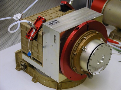 |
| ASPERA-3 Main Unit with the ELS protective cover removed. The NPI particle entrance and the two NPD entry ports are protected by red covers. Image courtesy of and © 2003 Swedish Institute of Space Physics |
Mechanical Scanner
The mechanical scanner sweeps the three sensors mounted on it through 180 degrees to give the
Digital Processing Unit
The Digital Processing Unit's main task is to control the sensors and the mechanical scanner. The DPU processes, compresses and stores the sensor data and forwards it (together with housekeeping data) to the spacecraft telemetry system. It also receives and implements commands sent to the
The primary design drivers for the Digital Processing Unit (DPU) are optimum use of the allocated telemetry rate and correct handling of telecommands. The
Neutral Particle Imager
In the Neutral Particle Imager, incoming particles pass between two 150 mm diameter discs, which are separated by 3 mm and have a 5 kV potential between them. Charged particles are deflected by the electric field and captured, but neutral particles pass between the discs. The space between the discs is divided into 32 sectors by plastic spokes, forming 32 azimuth collimators with an aperture of 9 degrees by 18 degrees each. Neutrals that pass through the deflector system hit a 32-sided conical target at a grazing angle of incidence (20 degrees). The interaction between the neutral particles and the target results in production of secondary electrons and ions, and / or reflection of the primary neutrals. The particles leaving the target are detected by a Micro Channel Plate (MCP) stack with 32 anodes. The signal from the MCP gives the direction of the primary incoming neutral particle. The MCP is operated in such a way as to detect sputtered ions of the target material, ions resulting from stripping of the primary neutrals and neutrals reflected from the target surface. In order to improve the angular resolution and collimate the particles leaving the interaction surface, 32 separating walls are attached to the target, forming a star-like structure. This configuration allows the particles to experience multiple reflections and reach the MCP. The target is specially coated to prevent incoming ultraviolet photons that strike it from producing erroneous results.
The Neutral Particle Imager covers 4π steradians in one
Neutral Particle Detector
The Neutral Particle Detector consists of two identical pinhole cameras each with a
The collimated Energetic Neutral Atom (ENA) beam emerging from the 4.5 × 4.5 mm pinhole hits a target at a grazing angle (20 degrees) and causes secondary electron emission. The secondary electrons are detected by one of two Micro Channel Plate (MCP) electron multiplier assemblies. The MCP output provides a start signal to the electronics that measures the time of flight of the ENAs over a fixed distance. The incoming ENAs are reflected from the target nearly specularly and travel to a second target. Again, secondary electrons are produced and detected by three more MCPs, which pass a stop signal to the time of flight electronics. The time of flight between the two targets gives the velocity of the incoming particle. Which of the three 'stop' MCPs detects the incoming particle determines its (instrument relative) azimuth direction.
Since secondary electron yield depends on both incident particle mass and velocity, the mass can be determined, given that the velocity is known, by analysing the height distribution of the pulses from the MCPs.
The effects of ultraviolet radiation are suppressed by coating the targets appropriately and checking for coincidence between the start and stop signals used for the time of flight calculations.
As the mechanical scanner moves the NPD through 180 degrees, a 2π steradian (half sphere) coverage of the incident particle field is obtained.
Electron Spectrometer
The Electron Spectrometer determines the energy spectrum of incoming electrons in each of sixteen 22.5-degree sectors.
The Electron Spectrometer is based around a spherical section electrostatic analyser of 'top hat' design. The electrostatic analyser consists of two concentric hemispherical electrodes, the outer of which has a central hole, through which electrons are admitted, covered by the 'top hat' and collimator. Electrons arriving from any azimuth angle and within the elevation field of view of the collimator pass under the 'top hat' and are deflected through the central hole in the outer hemisphere by a positive potential on the inner hemisphere. The electrostatic field between the hemispheres will deflect electrons having an energy in a particular range such that they travel between the electrodes. Electrons with energies outside the selected range will be captured.
These energy band filtered electrons exit the annular gap between the hemispheres and hit a Micro Channel Plate (MCP) electron multiplier. Beyond the MCP, the electrons strike one of sixteen anodes, each defining a 22.5 degree sector of incident azimuth angle.
By varying the electrostatic potential between the hemispheres of the electrostatic analyser, the energy of the electrons selected by the filter can be changed. The voltage applied to the inner hemisphere is swept once every four seconds and the number of anode hits per sample interval is recorded to give an energy spectrum for the incoming electrons in each sector. As the ELS sensor is moved through 180 degrees by the mechanical scanner, a complete 4π steradian (whole sphere) angular distribution of electrons is measured.
Ion Mass Analyser
The Ion Mass Analyser determines the mass spectrum of incoming ions in a selectable energy range. The mass range and resolution of the spectrum are also selectable.
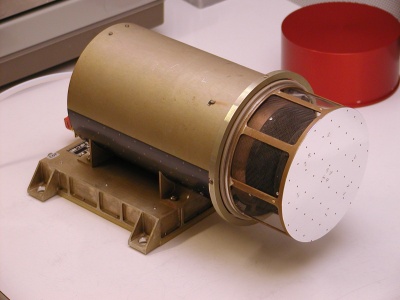 |
| ASPERA-3 Ion Mass Analyser with red protective cover removed to expose the particle entrance. Image courtesy of and © 2003 Swedish Institute of Space Physics |
Ions arriving at the IMA pass through an outer, grounded grid and enter the deflection system. The deflection system comprises two curved, charged plates that deflect ions arriving in the instrument elevation range from 45 degrees above to 45 degrees below instrument azimuth plane and from any azimuth angle into the entrance of the electrostatic analyser.
The electrostatic analyser consists of two concentric hemispheres with a variable electric field between them. Ions that lie within the energy pass band of the analyser travel between the hemispheres, exit the annular space separating them, and travel on towards the magnetic mass analyser. The electrostatic potential between the hemispheres determines the energy range of the ions that pass through the analyser.
In the magnetic mass analyser, the ions pass through a static, cylindrical magnetic field, which deflects light ions towards the centre of the cylinder more than heavy ones. An electrostatic potential can be applied between the electrostatic analyser and the magnet assembly to accelerate the ions. Varying this potential allows selection of the mass range to be analysed and the mass resolution.
As the ions leave the magnetic mass analyser they hit a Micro Channel Plate (MCP). The electrons exiting the MCP are detected by an imaging anode system. A system of 32 concentric rings measures the radial impact position, which corresponds to ion mass and 16 sector anodes measure azimuthal impact position, which corresponds to ion azimuth angle.
HRSC: High Resolution Stereo Camera
The High Resolution Stereo Camera (HRSC) is a multi-sensor pushbroom instrument comprising multiple charge coupled device (CCD) line sensors mounted in parallel for simultaneous high-resolution stereo, multicolour and multi-phase imaging of the Martian surface. An additional Super Resolution Channel provides frame images imbedded in the basic HRSC swath at five times greater resolution.
HRSC was originally developed for the Russian Mars 96 mission. Two fully tested and calibrated flight models were produced. The flight spare has undergone a modification process to make it fully compliant with the Mars Express interface requirements. Special emphasis has been placed on achieving low mass and power consumption.
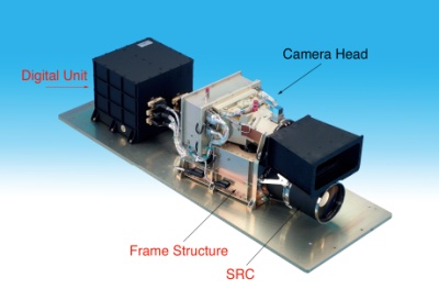
The HRSC instrument consists of two components, the Camera Unit (CU) and the Digital Unit (DU) connected by a wiring harness.
 |
|
The High Resolution Stereo Camera |
The Camera Unit consists of:
- The Instrument Frame, which is the supporting structure for the Camera Head and the SRC and provides thermal decoupling from the spacecraft and thermal stability
- The Camera Head, comprising the objective lens with its baffle and the optical bench, which serves as the central structure and connects the objective lens with the focal plate containing the Focal Plate Modules and the Front End Electronics
- The Super Resolution Channel, mounted within the Instrument Frame
The Digital Unit comprises a power converter supplying the digital processing electronics and the sensor electronics, a signal interface to the spacecraft, an instrument control processor and a data compression unit, all mounted in a single enclosure.
High Resolution Camera Head
The High Resolution Camera Head contains the optics, the optical bench, the spectral filters, the CCD line sensors, the sensor electronics, and a thermal control system.
The optics are of Apo-Tessar objective design with a focal length of 175 mm and f = 5.6, and are mounted in a titanium housing. The transmissivity of the optics varies from 0.37 for the blue channel (440 nm) to 0.68 in the panchromatic range.
The HRSC Camera Head contains nine CCD line sensors mounted in parallel for operation in pushbroom mode. Pushbroom or linear array sensors image a line on the planet surface perpendicular to the ground track of the spacecraft and rely on the orbital motion of the spacecraft to reposition them as they record a sequence of images known as an image swath. HRSC simultaneously provides high-resolution stereo, multicolour and multi-phase images of the Martian surface by delivering nine superimposed image swaths.
The Camera Head sensor electronics consists of three Focal Plate Modules (FPM), each of which contains three CCDs including drivers and preamplifiers, and a Front End Electronics (FEE) unit comprising four signal chains, nine focal plate controllers and one power distribution unit.
Each of the nine CCD linear arrays is made up of
Super Resolution Channel
The Super Resolution Channel (SRC) consists of a set of optics, a CCD array detector and the associated signal electronics.
The SRC optical system is a Matsukov-Cassegrain telescope with a focal length of 972 mm, positioned with its axis parallel to the optical axis of the HRSC Camera Head. The SRC sensor is a CCD array of 1024 × 1032 nine-micron square pixels, which correspond to 2.3 metre square pixels
The SRC has a mechanical interface with the HRSC Camera Head and an electrical interface with the HRSC Digital Unit. It has no direct interface to Mars Express and is treated by the spacecraft as an additional HRSC channel.
Multi Sensor Concept
The multi sensor concept of the HRSC combines stereo, multi-spectral and multi-phase imaging. High-resolution images from the SRC can be embedded in the pushbroom images
Stereo imaging is performed using nadir-directed, forward looking (+18.9°), and aft-looking (-18.9°) line sensors with a spectral range of 675 ± 90 nm. Known as triple panchromatic along-track stereo, this technique permits robust stereo reconstruction by on-ground digital processing and rectification through attitude reconstruction, feature matching and bundle adjustment, followed by the generation of digital terrain models and higher-level products. In general, the nadir-looking channel delivers the highest resolution images, while the two outer stereo channel images will be transmitted at lower resolution after pixel summation.
Multi-spectral imaging is implemented using four additional line sensors for the blue (440 ± 45 nm), green (530 ± 45 nm), red (750 ± 20 nm) and near infrared (970 ± 45 nm) colour ranges. These colour images cover the same areas as the panchromatic triple stereo images and will be matched geometrically to the nadir channel panchromatic swath by a process involving digital rectification through post-facto altitude reconstruction. In general, the multi-spectral images will be artificially decreased in spatial resolution by on-board pixel summation for lower data rates and better signal-to-noise characteristics, giving rise to data entities referred to as macro pixels.
Two additional panchromatic line sensors having inclined forward and backward viewing directions perform multi-phase imaging. These sensors complement the information contained in the triple stereo channels and allow the determination of photometric surface characteristics. The data from these channels will normally be transmitted at lower resolution by pixel summation.
The nine line sensing channels can be allocated to one of four signal chains. Each chain can be operated independently, offering great flexibility in the processing of the data.
When the SRC is operated, one of the four signal chains is dedicated exclusively to SRC and the line sensors use the remaining three signal chains.
Pushbroom Observations and Three Line Stereo Imaging
The Camera Head with its nine CCD line sensors is operated according to the pushbroom principle:
As the spacecraft moves along its ground track, all nine CCD line sensors are exposed for a chosen exposure time and at a selected scan frequency in such a way that a contiguous image strip, having no gaps between adjacent lines, is generated. The exposure time and the scan frequency are closely connected, with the readout time between adjacent lines being negligible. Nine independent image strips are generated. The size of an image strip is defined by the number of pixels per line and the acquisition duration. The cross track dimension (swath width) changes with spacecraft altitude whereas the along track size (strip length) is limited only by spacecraft resources such as memory available to store observation data and allocated downlink capacity.
In order to guarantee square pixels the scan frequency has to be varied with changing cross-track pixel size. Thus, the scan frequency depends on the cross track pixel size, which in turn depends on the spacecraft altitude. As a result the instrument data rate changes with spacecraft altitude, reaching its maximum at pericenter. The gain of the HRSC electronics is varied with the changing scan frequency in order to compensate for the variations in the amount of light reaching the CCDs as the exposure duration changes. For a spacecraft velocity over ground at pericenter of 4.3 kms-1 the scan frequency is 425 Hz. The scan frequency decreases as the spacecraft altitude increases.
During normal HRSC imaging, nadir pointing of the spacecraft is required. Off-track pointing, where the spacecraft is turned to position the instrument line-of-sight to one side of the ground track, may be used for the acquisition of special targets.
The nine CCD line sensors of the Camera Head are located behind a single optical system and each sensor sees the planetary surface with a different viewing angle, which forms the basis for stereo imaging.
Each image point is seen from three different viewing angles, forward-looking, nadir-direction and aft- looking. Given an accurate knowledge of the position and attitude of the spacecraft at the time of image acquisition, the absolute three-dimensional position of objects in the images can be calculated.
The distance on ground spanned by the stereo viewing angle (nadir to forward-looking or nadir to aft-looking, both 18.9 deg) is called base length. For in-track stereo reconstruction a minimum image strip length of three base lengths is required. At pericenter, this corresponds to an imaging duration of two minutes. To perform a robust stereo reconstruction over mosaics consisting of adjacent image swaths, a sideways overlap of about 20% of the swath width is required.
| HRSC characteristics | |||
| Parameter | HRSC | SRC | Remarks |
| Mechanical and electrical parameters | |||
| Mass (kg) | 20.4 | ||
| Power consumption (W) | 43.4 | 5.3 | During imaging |
| Electro-optical performance | |||
| Optics | Apo-tessar | Matsukov-Cassegrain telescope | |
| Focal length (mm) | 175 | 972 | |
| f number | 5.6 | 11 | |
| Stereo angle (deg) | -18.9, 0, +18.9 | - | |
| Along-track field of view (deg) | Stereo angle | 0.75 | |
| Across-track field of view (deg) | 11.9 | 0.75 | |
| Detector type | THX 7808B | Kodak KAI 1001 | |
| Detector pixel size (µm) | 7 × 7 | 9 × 9 | |
| Pixel size on ground (m) | 10 × 10 | 2.3 × 2.3 | At 250 km altitude |
| Pixel field of view (arcseconds) | 8.25 | 2 | |
| Active pixels per sensor | 9 sensors × 5184 | 1024 × 1032 | |
| Image size on ground | 52.7 km swath × [time] | 2.4 km × 2.4 km | At 250 km altitude |
| Radiometric resolution | 8 bits before compression | 14 bits or 8 bits | |
| Spectral filter wavelength ranges | |||
| Panchromatic (nm) | 675±90 | - | Nadir, 2 stereo, 2 photometric |
| Near-IR (nm) | 970±45 | - | |
| Red (nm) | 750±20 | - | |
| Green (nm) | 530±45 | - | |
| Blue (nm) | 440±45 | - | |
| Operations | |||
| Pixel exposure time (ms) | 2.24 - 54.5 | 0.5 - 50 000 | |
| Image size (km) | 53 × 330 | 2.4 × 2.4 | Typical value |
| Data volume per image (Mbit) | 230 | 8 or 14 | Typical value |
| Data volume (Gbit day-1) | ~ 1 | Typical value | |
| Operations duration (minutes) | 3 - 40 | Typical value | |
| Planetary coverage | ≥ 50% at ~15 m pixel size | > 1% at ~ 2 - 3 m pixel size | |
MaRS: Mars Radio Science
The Mars Radio Science experiment (MaRS) will perform the following experiments:
- Radio sounding of the neutral Martian atmosphere (occultation experiment) to derive vertical density, pressure and temperature profiles as a function of height, with a height resolution better than 100 meters.
- Radio sounding of the ionosphere (occultation experiment) to derive vertical ionospheric electron density profiles and to derive a description of the global behaviour of the Martian ionosphere through its diurnal and seasonal variations depending also on solar wind conditions.
- Determination of dielectric and scattering properties of the Martian surface in specific target areas by a means of a bistatic radar experiment.
- Measurement of gravity anomalies in conjunction with simultaneous observations using the High Resolution Stereo Camera to construct a three-dimensional topographical model for the investigation of the structure and evolution of the Martian crust and lithosphere.
- Precise determination of the mass of the moon Phobos.
- Radio sounding of the solar corona during the superior conjunction of the planet Mars with the Sun.
The spacecraft Telemetry, Tracking and Command (TT&C) radio links between the orbiter and the Earth will be used for these investigations. A simultaneous and coherent dual-frequency downlink at
The experiment relies on the observation of the phase, amplitude, polarisation and propagation times of radio signals transmitted from the spacecraft and received at ground station antennas on Earth. The radio signals are affected by the medium through which the signals propagate (atmospheres, ionospheres, interplanetary medium, solar corona), by the gravitational influence of the planet on the spacecraft and finally by the performance of the various systems involved both on the spacecraft and on ground.
Radio sounding of the atmosphere and ionosphere
As the spacecraft is entering and exiting occultation by Mars as seen from the Earth, the TT&C radio beam slices through the layers of the ionosphere and neutral atmosphere. The TT&C system is operating in the two-way mode, which means that the downlink frequencies are derived from the received uplink frequency. Changes in the received radio frequency measured with an accuracy of one part in 10-13 correspond to the detection of a change in the angle of refraction of radio rays in occultation experiments of the order of 10-8 radians.
The separation of the effects of the ionosphere and the neutral atmosphere on the radio link is feasible by using a dual-frequency downlink and due to the fortunate fact that the peak height of the ionosphere and the limit of the detectable neutral atmosphere are well separated in height.
Bistatic radar investigation of planetary surface properties
The bistatic radar configuration is distinguished from the monostatic by spatial separation of the transmitter (the spacecraft) and the receiver (ground station on Earth). It is a powerful tool for providing information about surface texture (roughness and slope) on scales comparable with the sensing wavelength (of the order of centimetres to metres). Bistatic radar may also be used to determine properties of the surface material, such as dielectric constant, through differential reflection of orthogonal polarizations. The bistatic radar geometry of an orbiting spacecraft is well suited to probing the surface of planets at a variety of latitude, longitude and incidence angles.
For a typical downlink bistatic radar experiment, the radio signal is transmitted from the spacecraft High Gain Antenna toward the planetary surface and is scattered from that surface. That part of the signal power that is reflected toward Earth is received at the ground station. Optimising performance of the bistatic radar experiments requires accurate prediction of the orbiter trajectory for the formulation of antenna pointing strategies and prediction of signal parameters such as Doppler shift and signal amplitude. In a quasi-specular experiment the antenna is then programmed to follow a locus of points for which surface reflection would be specular if Mars were smooth. From the data recorded along these specular point paths, surface roughness can be inferred from Doppler dispersion of the echo signal; the dielectric constant of the surface material can be inferred from the echo amplitude and/or polarization properties.
In a bistatic backscatter experiment, the spacecraft antenna is aimed exactly opposite to the Earth direction, a configuration which is often much easier to implement than dynamically tracking either moving or fixed points. As the antenna beam illuminates regions on the surface, coherent backscatter enhancements will cause ice-covered areas to appear extremely bright. Repeated tracks over the polar region can be used to define the boundaries of icy polar deposits or to monitor their changes as a function of time. The spatial resolution of the measurements is approximately equal to the projection of the HGA beam on the surface. The radio echo signal is received in the open-loop mode in two orthogonal polarizations (for example, Left Circular Polarization, and Right Circular Polarization), down-converted, sampled, and stored for further processing at investigating institutions.
Determination of the mass of Phobos
The objective of this experiment is the precise determination of the mass of the Martian moon Phobos and, if feasible, also of the low degree spherical harmonics of its gravity field. The shape and volume of Phobos will be determined using observations made by the cameras carried on Mars Express, allowing the bulk density of the moon may be derived.
The method of mass determination during close encounters with small bodies is well established. The gravitational attraction of Phobos will slightly disturb the trajectory of Mars Express. The difference between predicted trajectory (without Phobos) and the actually observed trajectory will lead to the determination of the attractive forces acting on the spacecraft and from them the mass of the moon. To make these measurements, the spacecraft is operating in two-way link mode with an
The observations will be performed each time the spacecraft encounters Phobos with a closest approach distance of less than 500 km.
Investigation of gravity anomalies
Gravity information can be obtained at all times when the spacecraft is using the two-way dual-frequency radio link and the spacecraft is close enough to the surface that gravity accelerations significantly affects the spacecraft velocity. Earth pointing of the HGA is required to maintain a continuous radio link. The coherent and simultaneous dual-frequency downlink allows the extraction of the dispersive effects on the downlink due to the interplanetary medium and the Earth's ionosphere. Doppler tracking data will be acquired at a rate of one sample per 10 seconds and ranging data will be collected at a rate of one point per 10 minutes.
Velocity contributions induced by attitude control movements of the spacecraft which result in a HGA motion relative to the line-of-sight to Earth may reach several mm s-1. Therefore, thruster activities and attitude control commands have to be recorded in order to reconstruct the attitude motion for later correction of derived LOS gravity accelerations.
The anticipated accuracy of an S/X-band two-way radio link is of the order
Solar corona sounding
Solar corona sounding will be performed using a two-way radio link. A dual-frequency downlink at
Superior solar conjunctions of Mars will occur in
Solar coronal sounding will be performed when Mars Express is within ten degrees elongation on either side of the solar disk (40 solar radii), which will occur from
Space segment
The Mars Express Orbiter Radio Science (MaRS) experiment makes use of the radio link between the orbiter and the ground station(s) on Earth. Frequency, amplitude and polarisation information will be extracted from the radio signal received in the ground station.
The
The
The simultaneous and phase coherent dual-frequency downlink at
Ground segment
The ground stations will include the tracking complexes near Perth, Australia (ESA, 35 m antenna), and the Deep Space Network in California, Spain and Australia (NASA, 34 m antenna). A tracking pass consists of typically eight to ten hours of visibility. Measurements of the spacecraft range and carrier Doppler shift can be obtained whenever the spacecraft is visible. In the two-way mode the ground station transmits an uplink radio signal at
The ground stations will employ a hydrogen maser frequency standard to achieve frequency stability of the order of
MARSIS: Mars Advanced Radar for Subsurface and Ionosphere Sounding
MARSIS (Mars Advanced Radar for Subsurface and Ionosphere Sounding) is a low frequency, nadir-looking pulse limited radar sounder and altimeter with ground penetration capabilities, which uses synthetic aperture techniques and a secondary receiving antenna to isolate subsurface reflections.
The operation altitudes for MARSIS are up to 800 km above the Martian surface for subsurface sounding and up to 1200 km for ionospheric sounding. In its standard operating mode, the instrument is capable of making measurements in 1 MHz wide bands centred at 1.8, 3.0, 4.0 and 5.0 MHz.
MARSIS functions by transmitting a linear frequency modulated chirp using a nadir-looking dipole antenna. The return signal is received on both the dipole antenna and a secondary monopole antenna oriented along the nadir axis. The secondary antenna has a null in the nadir direction and receives primarily the off-nadir surface reflections. This signal can be subtracted from the main received signal during ground processing to reduce surface clutter. Both received signals are down converted to range offset video signals before being passed to an analogue to digital converter. The resultant data are formatted by the MARSIS on-board digital processor and passed to the spacecraft for transmission to Earth.
MARSIS operates in the following modes:
- Subsurface Sounding
- Active Ionospheric Sounding
- Receive Only
- Calibration
MARSIS will perform Subsurface Sounding when the spacecraft is less than 800 km above the Martian surface. In the highly eccentric orbit selected for Mars Express, this corresponds to a period of about 26 minutes, allowing mapping of about 100 degrees of arc on the Martian surface per orbit. Over the nominal mission lifetime, extensive coverage at all latitudes will be possible. To achieve this global coverage MARSIS supports both dayside and nightside operations, although performance is maximised during the night (solar zenith angle above 80 degrees) when the ionosphere plasma frequency drops significantly and the lower frequency bands, which have greater ground penetration capabilities, can be used.
Active Ionospheric Sounding will be carried out during certain orbital passes when the orbiter is less than 1200 km above the surface, in order to gather scientific data on the Martian ionosphere.
Receive only mode will mainly be used to characterise, from an electromagnetic point of view, the environment in which MARSIS is working.
MARSIS will be operated in calibration mode periodically throughout the operational phase of the mission. The purpose of this mode is to acquire a limited amount of data in an unprocessed format. The unprocessed data is used to determine the characteristics of the adaptive matched filter computation that is used by the MARSIS processor to compress the dispersed echo signals from the planet surface and subsurface boundaries.
MARSIS is composed of three subsystems:
- The antennas
- The RF equipment (transmitter and receivers)
- The digital electronics
The receivers and digital electronics are housed together within the spacecraft. The transmitter electronics is housed in a separate box, also within the spacecraft.
The main transmit and receive antenna is a deployable dipole with two 20 metre elements, arranged so that its peak gain is in the spacecraft nadir direction. The clutter cancellation antenna is a seven metre long deployable monopole, arranged so that its gain null is in the spacecraft nadir direction. The clutter cancellation antenna is equipped with a low-noise preamplifier. Due to severe limitations on the available mass, the antennas are of a novel design, each consisting of a folding composite tube that supports a pair of wires constituting the conductive element of the antenna. The antennas are deployed by pyrotechnic release mechanisms.
The transmitter is connected to the primary antenna through an impedance matching network. The nominal operating frequency of the transmitter in the subsurface sounder modes is 1.3 to 5.5 MHz, with an instantaneous bandwidth of 1 MHz. For ionospheric sounding, the operating frequency varies between 0.1 and 5.4 MHz. The transmitter takes the chirp generated by the receiver/local oscillator electronics and amplifies it, delivering 5 W of RF power to the antenna.
The receiver electronics consists of the chirp generator/local oscillator and a dual channel receiver that down converts the received echoes. Each receiver channel has a selectable bandpass filter, a mixer, an amplifier chain, low-pass filtering and an analogue to digital converter. The output of the analogue to digital converters is passed to the digital electronics for processing prior to being sent to the ground station via the spacecraft's on-board data handling system.
The digital electronics is responsible for:
- Synthesis of the transmit chirp and local oscillator signals
- Control of the transmitter and receivers
- Processing of the digital data from the receivers
- Receipt and execution of telecommands from the spacecraft
- Transmission of formatted science, event and housekeeping data to the spacecraft
| MARSIS subsurface sounding mode characteristics | ||||
| Centre frequency (MHz) | 1.8 | 3.0 | 4.0 | 5.0 |
| Bandwidth (MHz) | 1.0 | 1.0 | 1.0 | 1.0 |
| Radiated power (W) | 1.5 | 5.0 | 5.0 | 5.0 |
| Transmit pulse width (µS) | 250 or 30 | |||
| Pulse repetition rate (s-1) | 130 | |||
| Minimum science data rate (kbps) | 18 | |||
| Maximum science data rate (kbps) | 75 | |||
| MARSIS ionosphere sounding mode characteristics | |
| Start frequency (kHz) | 100 |
| End frequency (MHz) | 5.4 |
| Number of frequencies | 160 |
| Transmit pulse length (µS) | 91.43 |
| Frequency step (kHz) | 10.937 |
| Pulse repetition rate (s-1) | 130 |
| Sweep duration (s) | 7.38 |
OMEGA: Observatoire pour la Minéralogie, l'Eau, les Glaces et l'Activité
Observatoire pour la Minéralogie, l'Eau, les Glaces et l'Activité (OMEGA) is an imaging spectrometer covering the visible and near infrared wavelength ranges. The instrument comprises two grating spectrographs, one working in the visible and near infrared range (VNIR channel), the other in the short wavelength infrared range (SWIR channel).
The OMEGA instrument is made up of two main components:
- A Camera unit (OMEGA-CAMERA or OMEC) comprising the VNIR and SWIR spectrographs and their associated signal electronics
- A Main Electronics (OMEGA-ME or OMEM) module responsible for the control and management of the instrument
| OMEGA performance summary | |
| Imaging capability | 128 contiguous, across track fields of view, each of 1.2 mrad, corresponding to < 500 m at periapsis |
| Spectral capability | 352 contiguous spectral channels to acquire the entire spectrum from 0.36 to 5.2 µm for each resolved pixel |
| Photometric capability | SNR > 100 over the full spectral range, allowing the identification of percentage absorptions and thermal variations |
Visible and Near Infrared Range (VNIR) channel
The VNIR channel is based on a push-broom imaging concept with a two-dimensional silicon charge coupled device (CCD) detector and a telescope covering an 8.8° total field of view that is defined by a slit placed in the focal plane of the telescope. Target radiation leaving the slit is dispersed onto the detector by a concave holographic diffraction grating. The spectrum of a pixel area on the observed target is dispersed along a column of the detector array while spatial resolution in the direction of the spectrograph slit is obtained across the lines of the array. The spectrograph slit is oriented perpendicular to the spacecraft track so the motion of the spacecraft provides the second spatial dimension of the image. During one exposure interval, the full spectrum of every spatial pixel along the slit is obtained. Successive exposures are combined as the spacecraft moves, with the exposure times selected so that a contiguous image swath at the desired resolution is obtained.
| VNIR channel characteristics | |
| Entrance optics | |
| Telescope | Refractive, double Gauss objective |
| Aperture (mm) | 15.6 |
| f number | 3.7 |
| Field of view (rad) | 0.154 |
| Slit width (µm) | 50 |
| Spectrometer | |
| Dispersive element | Concave holographic mirror grating |
| Groove density (mm-1) | 65 |
| Dispersion (Åmm-1) | 1071 |
| Grating size (mm) | 40 × 10 |
| Detector | |
| Type | Silicon CCD, Thomson TH 7863 |
| Size (pixels) | 384 × 288 |
| Pixel size (µm) | 23 × 23 |
| Maximum spatial resolution per pixel (mrad) | 0.4 |
| Instrument | |
| Spectral range (µm) | 0.36 - 1.05 |
| Spectral resolution (λ/Δλ) | 70 - 200 |
| Dynamic range (bits) | 12 |
Short Wavelength Infrared Range (SWIR) channel
The SWIR channel of the camera has two sub-channels fed by a common telescope, slit and collimator. The collimator output beam is split into two parts by a dichroic filter, covering the
The use of linear arrays as detectors leads to the use of a whiskbroom-imaging concept. A scanning mirror gives the cross-track field of view and the spacecraft along-track motion provides the second spatial dimension for the images.
| SWIR channel characteristics | ||
| 0.93 - 2.77 µm |
2.65 - 5.2 µm | |
| Telescope | ||
| Type | Cassegrain | |
| Focal length (mm) | 200 | |
| f number | 4 | |
| Primary mirror | Parabolic, 55 mm diameter | |
| Secondary mirror | Hyperbolic, 20.5 mm diameter | |
| Spectrometer | ||
| Dispersive element | Blazed reflective grating | Blazed reflective grating |
| Groove density (mm-1) | 180 | 120 |
| Incidence angle (deg) | -6.5 | -10.6 |
| Blaze wavelength (µm) | 1.7 | 3.8 |
| Detectors | ||
| Type | Photovoltaic linear array | |
| Material | Indium antimonide (InSb) | |
| Size (pixels) | 128 | |
| Pixel size (µm) | 90 × 120 | |
| Pixel pitch (µm) | 120 | |
| Instrument | ||
| Cross-track field of view (deg) | 8.8 | |
| Spectral resolution (nm) | 13 - 20 | |
| Dynamic range (bits) | 12 | |
PFS: Planetary Fourier Spectrometer
 |
|
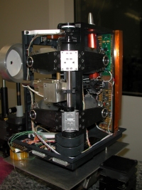
PFS Interferometer |
PFS is equipped with a pointing device, which enables it to receive incoming radiation from the surface of Mars or to perform calibration measurements by pointing to a reference black body of known temperature or to deep space.
The incident radiation arrives from the pointing device and is divided into two beams by a dichroic mirror and then filtered before being directed into the two interferometers. The interferometers are of the double pendulum type and are positioned with their planes of operation one above the other so that a single motor can be used to move both pendulums. An optical reference channel controls the pendulum motion by passing light from a laser diode through the same optics as the radiation that is being analysed. The reference channel also generates the sampling signal for the analogue to digital converters that process the detector signals, triggering one sample for each 150 nm of retro-reflector motion. The interferometers are extremely sensitive to optomechanical distortions and the interferometer module must be very rigid and thermally stable to minimise these effects.
| Summary of PFS Characteristics | ||
| Short Wavelength Channel | Long Wavelength Channel | |
| General | ||
| Spectral range (µm) | 1.2 - 5.0 | 5.0 - 45 |
| Spectral range (cm-1) | 2000 - 8000 | 230 - 2000 |
| Spectral resolution (cm-1) | 1.5 | 1.5 |
| Field of view (deg) | 2 | 4 |
| Detectors | ||
| Type | Photoconductor | Pyroelectric |
| Material | Lead selenide (PbSe) | Lithium tantalate (LiTaO3) |
| Shape / Size (mm) | Square / 0.7 × 0.7 | Circular / 1.4 (diameter) |
| Operating temperature (K) | 220 | 290 |
| Interferometer | ||
| Type | Double pendulum | |
| Reflecting elements | Cubic corner reflectors | |
| Beam splitter | Calcium Fluoride (CaF2) | Caesium Iodide (CsI) |
| Maximum optical path difference (mm) | 5 | 5 |
| Reference source | Laser diode | |
| Collecting optics | ||
| Type | Parabolic mirror | |
| Diameter (mm) | 49 | 38 |
| Focal length (mm) | 20 | 20 |
| Coating | Gold | |
| Channel separator | Thallium bromide/iodide | |
| Interferogram | ||
| Type | Two sided | |
| Sampling number | 16 384 | 4096 |
| Sampling step (nm) | 608 | 2432 |
| Dynamic range | ± 215 | |
The instrument is able to perform real time Fast Fourier Transform computations in order to select the spectral range of interest for data transmission to Earth.
SPICAM: Spectroscopy for Investigation of Characteristics of the Atmosphere of Mars
SPICAM (Spectroscopy for Investigation of Characteristics of the Atmosphere of Mars) is an imaging spectrometer for ultraviolet and infrared radiation. SPICAM is equipped with two channels, one for ultraviolet wavelengths and one for infrared.
| SPICAM Channels | ||
| Ultraviolet (SUV) | Infrared (SIR) | |
| Spectral range (µm) | 0.118 - 0.32 | 1.1 - 1.7 |
| Spectral sampling (nm per pixel) | 0.55 | 0.45 - 1.12 |
Operational Modes
The operational modes of SPICAM are Test mode (ground use only), Star mode, Sun mode, Limb mode and Nadir mode. The operational modes are derived from the scientific objectives and the related spacecraft attitudes.
| SPICAM Operating Modes | |
| Nadir mode | Used during spacecraft nominal nadir observation mode. SUV and SIR observing. |
| Star mode | Requires dedicated spacecraft attitude. SUV observing. |
| Limb mode | Requires dedicated spacecraft attitude. SUV and SIR observing. |
| Sun mode | Requires dedicated spacecraft attitude. SUV and SIR observing. |
In Nadir mode, the instrument will point directly at the planet and will analyse solar radiation that has travelled through the atmosphere after being reflected from the planet surface. Nadir observations allow the measurement of total column abundance of atmospheric components. In star or Sun mode, the instrument will point tangentially through the atmosphere towards a star, or the Sun, which is observed through the atmosphere as it rises or sets. The instrument then analyses the light once components of it have been absorbed by the atmosphere, allowing derivation of vertical concentration profiles for atmospheric components. In limb pointing mode, the instrument will point across the atmosphere, as during Star mode, but without a target star, and the instrument will analyse the vertical profile of aeronomic emissions.
Ultraviolet Channel
The SPICAM ultraviolet channel (SUV) is based around a holographic diffraction grating.
| Ultraviolet Channel Characteristics | |
| Usable dimensions of primary mirror | |
| Slit width | 0.05 and 0.5 mm |
| Slit length | 6.6 mm |
| Wavelength range | |
| Spectral dispersion | |
| Transmission of optics (Telescope + grating) | 30% |
| Pointing accuracy | Better than 0.2° |
| Detector | Intensified charge coupled device (CCD) |
| CCD dimensions | 384 × 288 pixels |
| CCD pixel size | |
| Field of view of one pixel | |
The first optical element in the UV channel is an off-axis parabolic mirror, which collects the incident light entering through either the nadir or solar aperture and focuses it.
| Ultraviolet Channel Mirror Characteristics | |
| Off axis portion of parent with origin at centre of parent paraboloid | |
| Focal length | 120 mm |
| Dimensions | |
| Entrance pupil dimensions | |
| Usable field of view | |
| Material | Aluminium |
| Coating | Magnesium Fluoride, MgF2 |
In the focal plane of the mirror, there is a slit, which can be moved in and out of the field of view by a mechanical actuator, providing two configurations:
- Slit absent, for observation of stellar occultations with a field of view of 1° x 3.16°
- Slit present, for the observation of extended sources
The slit has two parts, with two different widths, to give different flux resolutions.
The focal plane is the entrance of the spectrometer, a holographic concave grating, which collects the incoming light and directs it to the detector block.
| Ultraviolet Channel Grating Characteristics | |
| Type | Holographic |
| Shape | Toroidal |
| Coating | Magnesium Fluoride, MgF2 |
| Dimensions | |
| Radius of curvature | |
| Grooves per mm | 280 |
| Blaze wavelength | 170 nm |
| Incident angle | ~6.5° |
The detection block consists of a CCD detector equipped with an image intensifier tube. The spectrum of a single source point in the focal plane is dispersed along the lines of the CCD. The usable spectral band is 118 to 320 nm, chosen so as to offer good resolution (~1 nm) for stellar observations and to cover the CO2 and O3 bands. The lower wavelength was selected to be just below the Lyman α wavelength and the upper wavelength was chosen to reject visible light. The quantum efficiency of the photocathode is zero beyond 320 nm and the detector is therefore solar blind. The detector has a large dynamic range - by varying the gain of the image intensifier, the spectrometer can perform individual photon counting and deal with very high input intensities.
To observe the Sun, a five-millimetre diameter mirror is positioned so as to reflect the light from the Sun via a dedicated entrance aperture onto the parabolic mirror.
Infrared Channel
The SPICAV infrared channel (SIR) is based around a scanning acousto-optical tuneable filter (AOTF).
| Infrared Channel Characteristics | ||
| Diameter of primary lens | 30 mm | |
| Field of view | 1° (3x10⁻⁴ steradians) | |
| Slit width | 1 mm | |
| Wavelength range | ||
| Sampling per pixel | ||
| Transmissivity of optics | 25% | |
| Detector | InGaAs PIN photodiode | |
| Resolution at nadir | ||
The entrance optical system comprises a lens telescope with a diameter of thirty millimetres and a collimator lens, which collect the incoming radiation and direct it onto the AOTF.
The AOTF consists of a tellurium oxide (TeO2) crystal to which an acoustic wave is applied. The acoustic wave propagating in the crystal causes it to act in a similar way to a diffraction grating. A radio-frequency synthesizer drives a piezo-electric crystal attached to the TeO2 crystal to produce the wave. The frequency of excitation determines the wavelength of the acoustic waves and hence the select wavelength of the AOTF. The frequency range of the synthesizer corresponds to an AOTF passband
The two output beams from the AOTF are collimated by another lens and detected by two indium gallium arsenide PIN photodiodes.