Facilities
The Payload Validation Section benefits from state-of-the-art facilities in a laboratory space of about 1400m². The facilities include: optical test benches, cryogenic equipment including cooling systems and associated instrumentation, mechanical workshop, cleanrooms, and metrology, to name a few. This diversity provides the broad range of testing capabilities required to support the different types of programmes in the Directorate of Science.
Contents of this page
| Detector test benches |
| Electronic laboratory |
| Mechanical workshop |
| Software & IT |
| Cryogenics |
| Cleanrooms |
| Metrology |
| Plasma Chamber |
Detector test benches
CCD test bench'
ESA's science missions, for example, Gaia, CHEOPS, Euclid, and PLATO, make extensive use of CCDs as their main photon detectors. Depending on the scientific goals of the mission, different aspects of the CCDs' performance, such as, quantum efficiency, intrapixel photometric response, may be critical for achieving these goals. In this context we perform mission-specific tests in support of the CCD procurement and the payload development by the mission scientific consortium. To minimise risks during the decision-making process we also perform specific tests on short notice to address critical issues arising during, for instance, device operation or qualification.
To meet these goals, the section operates two CCD test benches (also known as cameras):
• a low-noise slow-readout (< 200 kHz) versatile camera using 4-channel analogue dual-slope integrator correlated double sampling (CDS) readout electronics (XCAM Ltd., UK)
• a high-speed readout (> 4 MHz) camera specially designed and built for the PLATO CCDs using 4-channel digital CDS readout electronics (STA Inc., USA).
The low-noise camera makes use of liquid nitrogen to cool the CCDs down to 120 K and the front-end electronics (pre-amplifiers) is located within the cryostat. The lowest readout noise figure reached on the Euclid device CCD273 with this system is below 2 e- rms. The high-speed camera relies on a cryotiger cooling system and can cool the CCDs down to 140 K, and the front-end electronics is located outside the vacuum chamber.
Both cameras can hold one or more CCDs up to at least 8×8 cm². The cryostats have fused silica-coated vacuum windows for optical illumination. The source can be either a uniformly illuminating integrating sphere, fed with tuneable (350-1050 nm) monochromatic light from a grating monochromator, or projectors (for sub-pixel size spots or masks with arbitrary scenes) mounted on 3-axis precision translation stages. Alternatively, the vacuum window can be exchanged for a metal flange that carries a radioactive 55Fe source with shutter, which allows for X-ray illumination with 5.9 keV photons.
The CCD cameras are controlled via dedicated Python scripts relying on the ESAPY library. Devices and processes under the control of the Python application are: the CCD controller, CCD and front-end electronics temperature controller, temperature readout, monochromator wavelength setting and filter selection, shutters, translation stages, and power read-out from reference photodiodes. The control software allows for a high degree of automated measurement series through nested loops of parameter variations. A test campaign can be fully automated.
The optical test benches are placed in dark rooms to limit external light pollution.
Publications:
CCD characterization for astronomy space missions at ESA
ESA's CCD test bench for the Euclid visible channel
ESA's CCD test bench for the PLATO mission
Near-infrared test bench
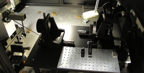
The optical test bench is dedicated to the measurement of the quantum efficiency and sub-pixel variations of detectors. It is composed of a 100W Quartz Tungsten Halogen (QTH) lamp, an optical chopper, a filter wheel and a double grating monochromator.
 |
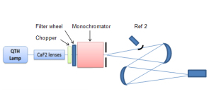 |
| Near-infrared test bench: (left) photograph of the laboratory bench and (right) schematic diagram of the layout. Credit: ESA | |
For the quantum efficiency measurements, two off-axis mirrors re-image the output of the monochromator. The power is then measured with Si, InGaAs or pyro-electric reference detectors.
For the sub-pixel measurements, a spot projector creates a diffraction-limited F/10 beam in the near-infrared wavelength range (up to 2.0 micron). The light entering the spot projector is provided via an optical fibre coming from the monochromator. A 3-axis translation stage allows the operator to scan the beam over the detector being tested.
Publications:
Large format array NIR detectors for future ESA astronomy missions: characterization and comparison
Mid-wave infrared test bench
To support potential future science missions, a test bench to validate the performances of Mid-Wave Infrared (MWIR) detectors up to 12µm is being developed. The objectives are to be able to measure the absolute quantum efficiency, dark current, and readout noise of such detectors.
A pulse tube cooler will host the detector allowing temperature down to 20K to be reached. The measurement of the quantum efficiency will be performed using a calibrated black body and cold filter.
A MWIR detector from CEA/LETI previously characterized for a previous activity will be used as a test vehicle. An ARC controller will read out the detector through a pre-amplifier board cooled to 90 K.
Electronic laboratory
The Payload Validation Section has the capability of performing electronic design (concept, simulation, schematic, layout) and manufacturing (PCB prototype production, vapour phase soldering, bake out). Qualified staff, who are expert in high-reliability hand soldering and inspection, are part of the team. All the necessary electronic measurement equipment is available. Solutions for analogue, digital and RF setups can be created based on the specific requirements.
 |
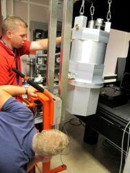
| Operational amplifier testing at -200°C. Credit: ESA |
 |
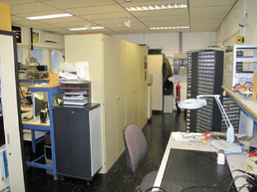 |
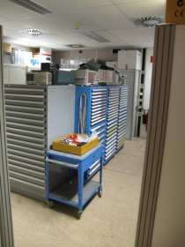
| Electronic laboratory facility with component storage units. Credit: ESA | |
Mechanical workshop
The mechanical workshop is essential to the operation of the Payload Validation Section, with the capability to design and manufacture end-to-end mechanical systems. Specific activities, such as coating, or manufacturing of large parts, are outsourced.
The design is carried out using CATIA software (2 workstations) and EdgeCam. The manufacturing capabilities include a 3-degree-of-freedom milling machine directly programmed via CATIA.
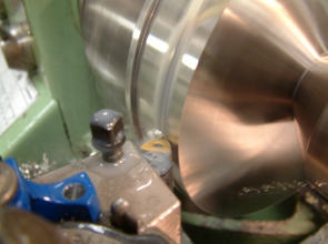
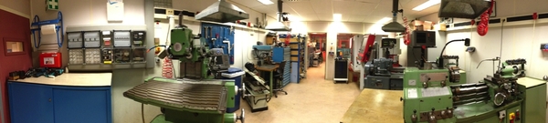 |
| Panoramic view of the mechanical workshop. Credit: ESA |
 |
 |
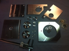 |
 |
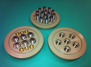
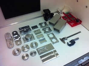
| Examples of mechanical parts created in the workshop of the Payload Technology Validation section. Credit: ESA | |
Software & IT
IT capabilities
The section uses its own server resources to handle the large volume of data produced. A large pool of computers dedicated to the control of the different experiments is maintained independently from the ESA corporate pool. Access to the computing grid of the ESA science faculty is also possible.
Software
One of the main tasks in the Payload Validation Section is to characterise sensors. This requires a specialized test bench that controls the sensor's environment, controls the stimuli to the sensor, and measures the sensor's response to these stimuli. Such a test bench requires a high degree of automation using computer-controlled instrumentation. This in turn requires sophisticated software to synchronize the communication and sequence of steps required in the automation process.
ESAPY is a software library that simplifies the building of applications to control and monitor test benches. It provides a set of packages that handle the following functionality:
- Low-level communication and simulation with instruments.
- Re-usable graphical components to aid in graphical user interface (GUI) development.
- Image analysis and processing
- Remote procedure calling (RPC) between remote applications.
ESAPY is written in Python (v2.7). The Python scripting language has proven to be very effective in developing such applications, because of features such as:
- Several GUI toolkits (Gtk, Qt)
- Very advanced and mature scientific libraries (SciPy, Matplotlib, NumPy)
- Easy access to instrumentation communication layers (PyVisa, ctypes)
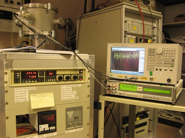
The ESAPY library was first used in the Payload Validation Section CCD test bench which is shown below:
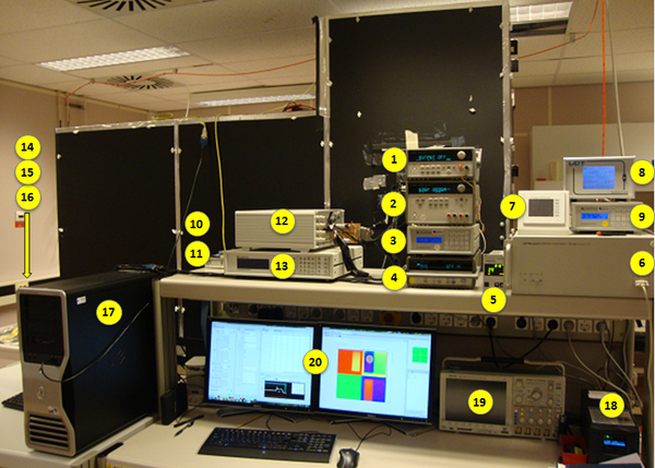 |
| Payload Technology Validation section CCD test bench. Credit: ESA 1. LED illumination controller (Agilent E3643A DC Power Supply) 2. Not used: Heater supply (Agilent E3648A Dual Output DC Power Supply) 3. CCD temperature controller (Lakeshore 325 #1) 4. Temperature DAQ monitor (Agilent 34970A) 5. Vacuum pressure monitor (Pheiffer Single Gauge) 6. XYZ stage controller (Newport Motion Controller XPS) 7. Manual XYZ driver (Newport XPS driver) 8. Optical power monitor (UDT S490 flexOptometer) 9. FEE temperature controller (Lakeshore 325 #2) 10. XCAM rack signal adapter 11. Internal shutter controller 12. XCAM rack 13. Not used: Temperature controller (Lakeshore) 14. Light source for monochromator (Newport) 15. Monochromator (Newport Cornerstone 130) 16. Fast shutter (Oriel 76995 Fast Shutter) 17. EGSE Computer (Dell T7400 Win7 64bit O/S) 18. APC Smart-UPS 19. Oscilloscope (Tektronics) 20. Dual Computer Monitor |
The GUI that is used to access the software to control the instrumentation is shown here:
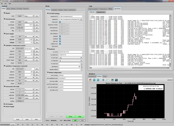 |
| GUI used to interface with the Payload Technology Validation section CCD test bench. Credit: ESA |
The automated measurement and sequencer is shown here:
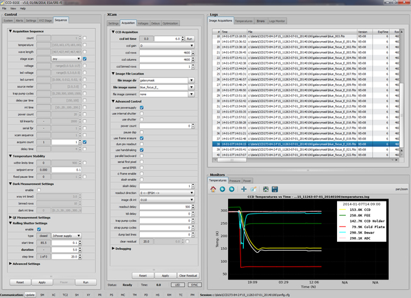 |
| Automated measurement and sequencer for the Payload Technology Validation section CCD test bench. Credit: ESA |
The GUI is dynamically generated based on configuration files. This means that applications can be quickly adapted to new requirements without having any major impact on the existing system.
Cryogenics
Some of ESA's past astronomy missions (for example, Herschel and Planck) and future space science missions (for example, Athena)have made or will make use of cryogenically cooled detectors, i.e. those operating at temperatures ranging from a few K to as low as 0.1K. The Payload Verification Section provides support on issues related to cryogenic payload performance. For that purpose the section has a range of coolers and cryostats, as well as relevant experience through the operation of this equipment in a long duration development programme of Superconducting Tunnel Junctions as detectors for high resolution X-ray spectroscopy and low resolution photon-counting imaging astronomy (S-CAM).
These coolers include:
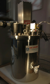
- A liquid helium cooled top-loading Heliox 3He sorption cooler (Oxford Instruments): this cryostat has a small sample space that can accommodate material samples or small detector chips for fast turn-around experiments. A well-controlled axial magnetic field can be applied. The operating temperature can be controlled in the range of 0.30-1.2K, and the sample stage allows for optical illumination (through a fibre) or X-ray illumination (through a radioactive source).
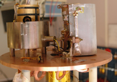
- A liquid helium cooled Adiabatic Demagnetization Refrigerator, ADR, (Cryogenic Spectrometers, model T60S) with a base temperature <50 mK and a hold time of about 10hrs at 100 mK. In addition to the magnetic field option and the fibre and X-ray illumination options of the Heliox, the ADR also has a radiation access port that allows for coupling to an external light source, e.g. an X-ray beamline in a synchrotron facility.
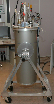
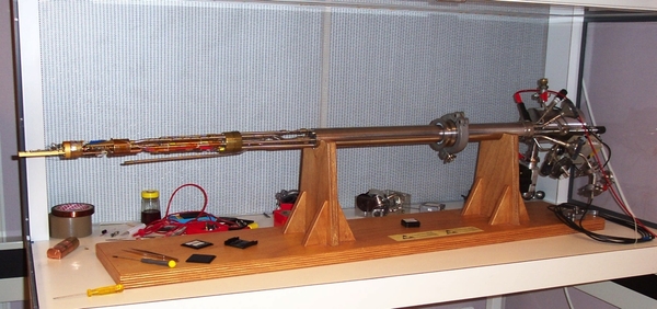
- A two-stage Pulse Tube Refrigerator, PTR, (Cryomech model PT405AL) with a base temperature of 4K and an intermediate stage at 60K. The cryostat has a large sample space that can accommodate further cooling stages such as 3He-4He 2-stage or 3-stage sorption coolers (Chase Research Cryogenics Ltd, model CRC10) for a lowest operating temperature of 260 mK. This cryostat also has the options of optical fibre and X-ray illumination as well as a small external radiation port.
- Several liquid helium or liquid nitrogen cooled portable cryostats (Bradford Engineering) with large radiation access ports and large sample spaces. Like the PTR, these can be equipped with 3He-4He 2-stage or 3-stage sorption coolers for a lowest operating temperature of about 300 mK.
- A liquid helium cooled top-loading KelvinoxTM Dilution Refrigerator (Oxford Instruments): this cryostat offers the same illumination and magnetic field options as the Heliox, but at a much lower base temperature of about 20 mK.
 |
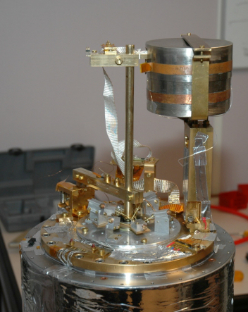 |
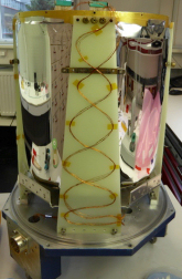
| Left: A liquid helium cooled Adiabatic Demagnetization Refrigerator (ADR). Right: The sample space in the ADR. Credit: ESA | |
 |
 |
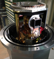
| Left: A two-stage Pulse Tube Refrigerator. Right: The sample space in the PTR. Credit: ESA | |
 |
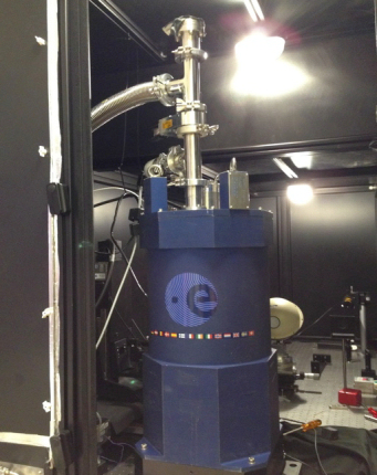
| Heliox cryostat. Credit: ESA |
Additional coolers currently used for CCD, near-infrared, and electronic testing, include:
- Liquid nitrogen based cryostats
- Mechanical coolers: cryotiger, CTI cooler
 |
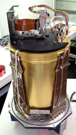 |
| Liquid nitrogen based cryostat used to test the CCD273 device. Credit: ESA | |
  |
 |
|
| Left: Liquid nitrogen based cryostat used for the near-infrared detector tests. Right: the HAWAII-2RG device is mounted in the cryostat. Credit: ESA | ||
Cleanrooms
The Payload Validation Section has access to five cleanrooms, from a class 3 to class 8. These cleanrooms are used to integrate or inspect components. Particle counters placed in the working areas and temperature sensors provide year-round monitoring of the room cleanliness.
A vacuum oven located in one of the cleanrooms is used to bake out components before integration into the cryostats.
 |
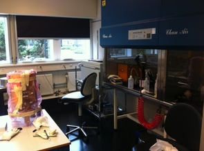 |
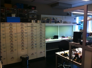
| Cleanroom with storage and cleaning bench. Credit: ESA | |
 |
 |
| Left: Near-infrared detector in cryostat for tests, in the cleanroom. Right: Inspection table in the cleanroom. Credit: ESA | |
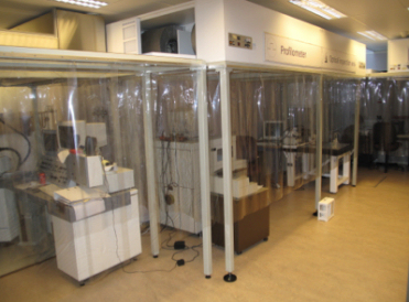
PAC (Particulate Contamination) is monitored regularly in all cleanrooms. In one of the clean tents, constant particulate monitoring is performed. MOC (Molecular Contamination) is addressed by dedicated witness plates mounted in each cryostat. The witness plates are changed after each cryo-cycle. The analysis of the witness plates by FTIR (Fourier Transform Infrared Spectrometer) is performed at ESA's establishment in the Netherlands (ESTEC) in the Product Assurance & Safety Department (TEC-Q) laboratories.
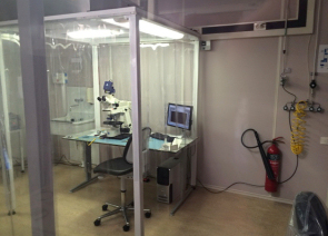
Metrology
A number of metrology tools are available:
- High-resolution microscopy (SteREO Discovery V20 Zeiss)
- Hall effect IC probe (Suess)
- Profilometer (Veeco DektakV200-Si)
All equipment is located in a cleanroom environment. Additional tools, such as a bonding machine, are also used.
 |
 |
| Left: Metrology clean tents. Right: The Veeco Dektak V200-Si is an advanced surface profilometer that measures surface texture below submicro-inch and film thickness to 262 um with high accuracy. Credit: ESA | |
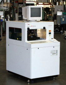
Plasma Chamber
.jpg) |
| A plasma chamber (with main aperture facing) in the Payload Technology Validation section laboratories. Credit: ESA |
The plasma chamber has been used for previous flight programmes involving Langmuir probes (m-NLP), on board the DEMETER spacecraft, and most recently, Cubestar. The facility was developed in the 1990s; it has been recently refurbished and is operational.