Service Module
Summary
Mechanical Service Module
 |
|
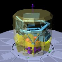
Diagram of the Gaia spacecraft, with parts made transparent to reveal different elements |
The mechanical service module is optimised so as to guarantee the stability of the basic angle, necessary to meet science requirements. It comprises a flat and uniform deployable sunshield which prevents Sun illumination of the spacecraft - and specifically the payload module (PLM) - during the nominal mission. The thermal tent enclosing the PLM caters for additional protection of the scientific instruments.
The spacecraft main structure is of hexagonal conical shape. It is a sandwich panel structure with carbon-fibre reinforced plastic (CFRP) facesheets, and a central cone supporting the propellant tanks.
It also features the passive and active thermal control system, as well as the thrusters of the chemical propulsion system and the complete micro-propulsion system.
Electrical Service Module
The electrical service module design is driven by the science performance (attitude control laws with the hybridisation of star tracker and payload measurements, high rate data telemetry, and regulated power bus for thermal stability). It houses the AOCS units, the communication subsystem, central computer and data handling subsystem, and the power subsystem.
 |
|
Diagram of the electrical service module. |
Thermal Control
A deployable Sun shield with optimal thermoelastic behaviour, made of multi-layer insulation sheets, is attached to the service module and folded against the payload module for the launch. After separation of the Gaia spacecraft from the launch vehicle, the Sun shield is deployed around the fixed solar array, in the same plane.
A thermal tent covers the payload, offering extra protection against micrometeoroids and radiation.
The very high stability thermal control is mostly passive and is achieved through optical surface reflector material, multilayer insulation sheets on the outer faces of the service module, and a black painted cavity, supplemented by heaters where required. Thermal stability is guaranteed by a constant solar aspect angle and the avoidance (as far as possible) of any equipment switch-ON/OFF cycles during nominal operation.
Electric Power
The spacecraft is equipped with a 12.8 m² high-efficiency triple-junction Gallium-Arsenide cell solar array, of which 7.3 m² is in the form of a fixed solar array and 5.5 m² is covered by 6 panels mechanically linked to deployable sunshield assembly.
For the launch, the deployable sunshield is folded against the payload module. After separation from the launch vehicle it is deployed around the fixed solar array, in the same plane. During the Launch and Early Operations Phase (LEOP), power is supplied by a 60 Ah mass-efficient Lithium-ion battery.
Optimum power supply during all phases of the mission is ensured by a power control and distribution unit with maximum power point tracking.
Propulsion
After injection into the L2 transfer orbit by the Soyuz-Fregat launcher, a chemical bi-propellant propulsion system (8 × 10 N) is used for the transfer phase. It will cover attitude acquisition, spin control, mid-course corrections, L2 orbit injection, and safe mode.
After arriving at L2, one redundant set of micro-propulsion thrusters will control the spin and precession motion of the spacecraft. Regular orbit maintenance will be performed by using the chemical propulsion thrusters.
The spacecraft uses a cold gas micropropulsion system for fine attitude control.
Attitude and Orbit Control
The AOCS subsystem is characterised by:
- High precision 3-axis control
- The ASTRO instrument is used for precise rate sensing during the fine pointing operational mode
- A high precision gyro is used for quick and efficient transitions during the fine pointing operational mode
- Rugged flight-proven initial acquisition and Safe modes
- Three Sun acquisition sensors plus one gyroscope provide spin-axis stabilisation during the L2 transfer phase of the mission
- One large field of view star sensor plus use of the main instrument sky mappers for the 3-axis controlled operational phase
Communications
All communication with the Gaia spacecraft is done using the X-band.
For telemetry and telecommand, low gain antenna up- and down-links with a few kbps capacity and an omni-directional coverage are employed.
The science telemetry X-band down-link is based on a set of electronically-scanned phased array antennae accommodated on the service module bottom panel. This high gain antenna is used during each ground station visibility period of about 8 hours per day.
Nominal spacecraft control during the routine mission phase will be done off line - contacts between the Mission Control Centre at ESOC and the spacecraft, except for collecting payload and housekeeping telemetry, will primarily be used for pre-programming of the autonomous operations functions on the spacecraft (up-link of mission timeline), and for science data collection.
Data Handling
The on-board command and data management subsystem is characterised by:
- An ERC-32 based central computer and distinct input/output units for efficient software development
- Two segregated MIL-STD-1553 B data buses: one for the payload module and one for the service module
- SpaceWire data links for high-speed payload data
- FDIR architecture aiming at preserving payload integrity, with built-in autonomy for increased availability
