#4: Simulating zero gravity
2 August 2019
Like most spacecraft, ESA's Solar Orbiter carries a number of deployable structures that play key roles in the success of its mission. Earlier this year, engineers completed a series of deployment tests on the spacecraft's antennas, instrument boom and solar arrays.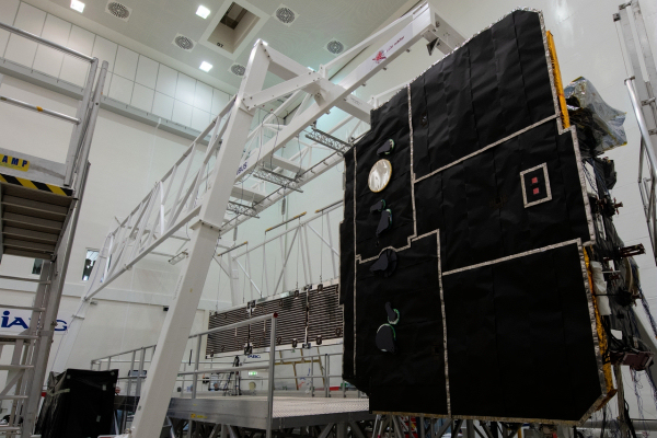 |
| Solar Orbiter array deployment test. Credit: ESA – S. Corvaja |
After completion of the vibration and acoustic tests carried out on the spacecraft at the IABG facility in Ottobrunn, Germany (see Solar Orbiter journal #3), the functional verification of Solar Orbiter's deployable structures began in March with the medium gain antenna (MGA) and high gain antenna (HGA), followed by the instrument boom and the two solar array wings.
Antenna deployments
Solar Orbiter will carry steerable high gain and medium gain antennas. The dish-shaped high gain antenna (see also Solar Orbiter journal #1) provides the primary communication link between the spacecraft and ground stations at the greatest distances from Earth. It ensures that the science data collected in the vicinity of the Sun is safely communicated back to Earth.
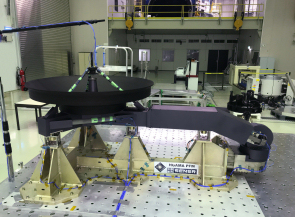 |
| The High-Gain Antenna during earlier vibration testing in May 2018. Credit: SENER Aerospace / European Test Services |
A pointing mechanism allows rotation of the HGA in azimuth (side to side) and elevation (top to bottom), to ensure that Earth is always in the line of sight when, for instance, the centre line of the spacecraft is pointing directly at the Sun.
During the Solar Orbiter mechanical test campaign, the HGA was released from its stowed configuration by using four low-shock, non-explosive actuation devices (NEAs).
Constructed from titanium and fitted with internal support struts, the HGA is optimised for operation in the weightless environment of outer space, so a device that would counteract its weight was required during the deployment test. This was a single cable connected to the extended parts of the dish, with a compensation mass to ensure that the loading was nearly zero at the point where it was attached to the spacecraft.
Once this offload calibration system was set up, the deployment began with the first activation of four NEAs. Additional NEA releases followed.
After each successful release initiated by the spacecraft's onboard control system, the test team confirmed that the data had been recorded at approximately 200 locations on the spacecraft, in order to measure how the shocks permeated into the spacecraft structure. This information was recorded to ensure that the measured shock levels were always less than the equipment or instruments were originally tested for.
The deployment of the horn-shaped MGA was tested in exactly the same way as the HGA – by means of an offloading mechanism. The full deployment of the antenna in elevation was achieved by activating its single NEA and recording the shock levels. The antenna pointing mechanism was deployed to its maximum extent during this test.
The deployment of both antennas required keeping their centre of gravity at the same height relative to the ground, so the antenna swung out parallel to the ground as the spacecraft was rotated on its side.
Instrument boom deployment
The instrument boom (I-Boom) comprises two sections, each 2 m in length, that are stowed against the spacecraft in the launch configuration.
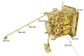 |
| Payload accommodation onboard Solar Orbiter. Credit: ESA |
In space, the spring-actuated boom is deployed so that the four science detectors mounted along it – part of the Solar Wind Plasma Analyser (SWA), Magnetometer (MAG), and Radio and Plasma Waves (RPW) instruments – are located away from the main spacecraft. This prevents magnetic and electrostatic interference from the platform as they perform their measurements.
The boom has two planes of deployment, making it impossible to deploy both sections when it is mounted on the spacecraft in the test chamber. The full deployment testing was completed on each section, when the ground support rig could be used to test both deployment planes, whilst it was removed from the spacecraft.
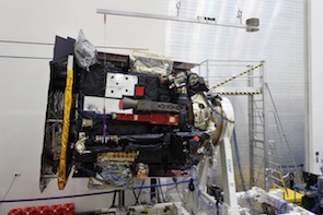 |
| Solar Orbiter instrument boom deployment test. Credit: Airbus Defence and Space/Sener Aerospace/IABG |
In addition to shock measurements, this test was designed to ensure that the initial deployment did not snag any of the external structures or surfaces of the platform.
This was achieved by setting up the spacecraft so that the plane of deployment was again parallel to the ground. A cable and mass compensation system balanced the set-up so that the hinge loads at the base were minimised.
During this first phase, both booms were deployed, but remained linked. The sections were held together by one of three hold-down-and-release mechanisms (HDRMs). The other two HDRMs had to be fired first before the boom composite sprang outward and rotated through more than 180 degrees. The entire deployment took less than 1 minute.
Solar array deployment
The two solar array wings on the spacecraft, each made up of three panels covered by solar cells, are also stowed and mounted on either side of the spacecraft via HDRMs. Each HDRM is basically a preloaded Kevlar rope, which is eventually cut by a heated knife. This 'thermal knife' technique is commonly used on spacecraft. The Kevlar rope is stored in a titanium housing and offers stable support for the solar arrays so that they can survive the rocket launch, when the loads are at their heaviest.
Solar panels provide electrical power and are some of the most delicate items on any spacecraft. In the case of Solar Orbiter, there are 6 HDRMs per panel, each housing a low-shock release device.
Although Solar Orbiter has been designed to utilise such devices, there is still the potential to damage the delicate instruments mounted on the spacecraft. By firing each set of 6 HDRMs, the tests demonstrated that the solar arrays could survive and deploy successfully after the vibrations endured during the launch.
| Solar Orbiter array deployment test. Credit: Directed by Stéphane Corvaja/ESA, Edited by Manuel Pédoussaut/Zetapress. (Click here for details and large versions of the video.) |
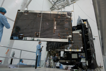
Support of the deployed solar array wings was essential, because the deployed arrays stretch outward some 8 m from the main spacecraft and are unable to support their own weight on Earth.
A ground support rig was used to provide the apparent weightless environment for each wing during deployment tests. This large structure supported a set of cables and compensation springs, two attached to each panel, which were themselves attached to frictionless air bearings in the upper parts of the rig. Once the effects of gravity were calibrated for the wing, this effectively suspended the deployed wing while simulating the weightless environment of space.
The air bearing allowed movement in two directions – both parallel to the ground – so that the panels were completely unhindered during deployment. Since all of this hardware is required for any operation to mount or dismount the wings, it will also be transported to the launch site.
 |
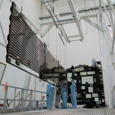 |
| Solar Orbiter array deployment test. Credit: ESA – S. Corvaja | |
Each wing remained connected to the spacecraft via its solar array drive mechanism. Once in space, this mechanism rotates the wings relative to the Sun in order to maintain the required power output and keep the temperature within acceptable limits around closest approach to the Sun.
Added complications include ensuring that instruments are directly aligned on the centre of the Sun at all times, to a high degree of accuracy (less than one tenth of a degree), whilst balancing the power and temperature limits of the solar array wings.
In total, the spacecraft had to survive 19 different shocks created during deployment of the solar arrays, I-Boom and antennas. Each shock affected different areas, groups of instruments and equipment.
All of the deployment tests on Solar Orbiter were successfully carried out in mid-March, with no detection of problems related to snagging or impeding of the hardware by insulation or other structures. Completion of these tests, along with previous environmental tests (see also Solar Orbiter journal #2), provides confidence that all of the deployable elements are ready for launch.
About Solar Orbiter
Solar Orbiter's mission is to perform unprecedented close-up observations of the Sun. Its unique orbit will allow scientists to study the Sun and its corona in much more detail than previously possible, and to observe specific features for longer periods than can ever be reached by any spacecraft circling the Earth. In addition, Solar Orbiter will measure the solar wind close to the Sun, in an almost pristine state, and provide high-resolution images of the uncharted polar regions of the Sun.
It will carry 10 state-of-the-art instruments. Remote-sensing payloads will perform high-resolution imaging of the Sun's atmosphere – the corona – as well as the solar disk. Other instruments will measure the solar wind and the solar magnetic fields in the vicinity of the orbiter. This will give us unprecedented insight into how our parent star works, and how we can better predict periods of stormy space weather, which are related to coronal mass ejections (CMEs) that the Sun throws our way from time to time.
Scheduled for launch in February 2020, Solar Orbiter will take just under two years to reach its initial operational orbit, taking advantage of gravity-assist flybys of Earth and Venus, and will subsequently enter a highly elliptical orbit around the Sun.
Solar Orbiter is an ESA-led mission with strong NASA participation.


