STE-QUEST Science Instrumentation Q&A
For each entry the date is stated for when it was added to this page. Some answers refer to details provided in the Call documentation. These documents are available through the Call web page, which is linked from the right-hand menu, and can also be accessed at: http://sci.esa.int/ste-quest-doi2011
| 7 Oct 2011 - Clock subsystem input signal | |
| Q-1: | Is it assumed that the Clock subsystem will receive an input signal from an external USO? |
| A-1: |
This issue has been discussed in the STE-QUEST science team. Both the atomic clock and the atom interferometer are expected to have two operational modes:
This is also specified in the STE-QUEST Science Requirements document: see #SR-PL-10 for the atomic clock and #SR-PL-14 for the atom interferometer. |
| 7 Oct 2011 - Clock subsystem signal distribution | |
| Q-2: | The Clock subsystem provides a 1064 nm optical reference to the optical link. Is it necessary, as stated, that this signal be distributed by the FGCD unit? |
| A-2: | Certainly not. The PDD is only providing guidelines for the instrument architecture and in this specific case there is no real need to have the optical signal going through FGCD. |
| 7 Oct 2011 - Payload support strut measurements | |
| Q-3: | Additional information on the four feet that carry the upper part of the payload would help to better define the PHARAO-Rb clock accommodation. Is such a description available? A 3-D file of this structure would of course be ideal. |
| A-3: | 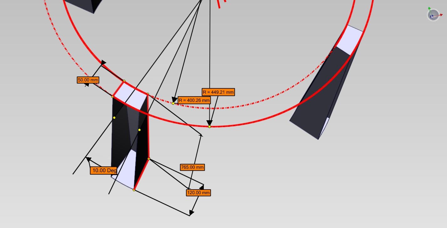 Some additional information is provided in the image on the right. However, it should be kept in mind that the design study conducted in the frame of the ESA CDF is very preliminary and is subject to change in the course of the assessment phase. Some additional information is provided in the image on the right. However, it should be kept in mind that the design study conducted in the frame of the ESA CDF is very preliminary and is subject to change in the course of the assessment phase. |