Wide Field Imager
Mission Architecture
A mission concept was identified that consists of a 2000 kg spacecraft launched by a Soyuz-Fregat into a L2 halo orbit. The operational orbit at L2 is selected to maximize the observing efficiency and to provide a stable thermal environment. The nominal mission lifetime is 3 years, plus a possible 3-year extension.
Scientific Objectives
 |
|
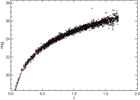
Figure 1. WFI magnitude versus redshift diagram of SN Ia. (Credit: ESA) |
The Wide Field Imager will search for Type Ia supernovae (SN Ia) at low redshift in the optical and near IR part of the spectrum with the aim of measuring the changing rate of expansion of the Universe and determining the contributions of decelerating and accelerating energies such as the mass density, the vacuum energy density and other yet-to-be-studied dark energies.
The WFI measurements will be used to establish a Hubble-diagram plot (redshift versus peak magnitude) of SN Ia at low redshift (see Figure 1). The comparison of SN Ia redshift and peak brightness (magnitude) provides a measurement of the changing rate of expansion of the Universe: the apparent magnitude indicates the distance and hence time back to the supernova explosion, while the redshift measures the total relative expansion of the Universe since that time. The objectives of the WFI mission are therefore
- to search for SN Ia in the optical and near IR part of the spectrum,
- to determine the maximum brightness of their light curves, and
- to measure the red-shifts of their host galaxies
By fitting the obtained Hubble diagram with models, the WFI mission will be able to determine the contributions of decelerating and accelerating energies - mass density ΩM, vacuum energy density ΩΛ, and/or other yet-to-be-studied dark energies as the expansion rate changes over time.
The WFI could analyse up to a few thousand supernovae with redshifts ranging from 0.3 to 1.8. For each object, the spacecraft's telescope and instrumentation shall provide:
- early detection of the supernova
- B-band rest-frame photometry along its light curve
- colour determination near its peak brightness
- identification of the supernova type using optical and IR spectroscopy at peak brightness
- photometric red-shift measurements of its host galaxy
Payload Definition
To accomplish the science goals, the WFI reference payload consists of
- a 2-meter class telescope with a large 1.0° × 1.0° field-of-view,
- a wide field camera sensitive to wavelengths from 350 nm - 1800 nm, and
- a low resolution integral field spectrometer operating in the same spectral range.
Telescope
The optical configuration of the WFI telescope consists of a three-mirror design with two folding flats that provides a large unvignetted field of view corrected for spherical aberration, coma and astigmatism.
| WFI telescope performance requirements | |
| Primary mirror aperture | 2.15 m |
| Focal length | 20 m |
| Field of view | > 1° × 1° |
| Spatial resolution | Diffraction limited at 1 mm |
| Spectral coverage | 350 nm to 1800 nm |
| Plate Scale | 0.1 arcsecond per 10 mm |
| Survey fields | Ecliptic poles |
| Solar avoidance angle | > 70° |
| Relative pointing error | 10 milli-arcseconds |
| Operation temperature | ~290 K |
Camera
The WFI camera uses two detector technologies. The near- infrared (NIR) range (900 nm to 1800 nm) is measured with 72 HgCdTe arrays of 1450 × 1450 pixels each with a pixel pitch of 20 µm. The visible region (300 nm to 1000 nm) could be measured with deeply depleted back illuminated p-channel CCDs that are radiation hard. 72 such arrays with a 2900 × 2900 pixels each and a 10 µm pixel size would be needed. The camera's large (~ 40 cm × 40 cm) focal plane array (FPA) will be covered with 18 NIR filters and 72 visible filters deposited onto or in front of the detectors. Each line and each column of the FPA shall contain nine different filters.
Spectrometer
An integral field spectrometer with an image slicer is a candidate concept for the WFI spectrometer. The image slicer eliminates the need for a slit and greatly reduces the pointing accuracy required to place the supernova within the field of view of the spectrograph while preserving photometric accuracy because of its 100% filling factor. The spectrograph shall have a visible and near-IR arm within a single instrument. Its spectral resolution could be of the order of a 100 and its field of view of about 3 × 3 arcseconds. The maximum number of slices limited by diffraction would be about 15 in the near-IR and 30 in the visible. Gratings or prisms could be used as dispersive elements and the spectrometer camera could also benefit from the p-channel CCD and HgCdTe detector technology.
| WFI detector performance requirements | ||
| Visible detector | NIR detector | |
| Technology | P channel CCDs | HgCdTe |
| Spectral coverage | 300-1000 nm | 900-1800 nm |
| Array format | 2900 × 2900 pixels | 1450 × 1450 pixels |
| Pixel sixe | 10 μm | 20 μm |
| QE | > 80% | > 60% |
| Read-out noise | 4 e- @ 100kHz | 5 e- |
| Dark current | 0.005 e-/s/px | 0.02 e-/s/px |
| Exposure time | 8 × 125 s | 64 × 15.6 s |
| Read-out time | ~ 20 s | ~ 40 s |
Spacecraft
 |
|
Figure 2. Cut-away view of the WFI spacecraft design, showing the light path through the telescope. (Credit: ESA) |
Service Module
The WFI service module consists of an hexagonal structure that carries the power subsystem with 6 m² of GaAs solar cells, the telecommunication subsystem with a 0.4 m diameter high gain antenna, the propulsion subsystem with a monopropellant tanks, and the attitude and orbit control subsystem.
Payload Module
The Payload Module consists of the telescope and the two instruments: the camera and the spectrometer. The telescope structure is organized around an optical bench that carries the M1, M3 and M4 mirror isostatic supports and the tripod interface to the secondary mirror. The optical bench also carries the instrument bay that contains the last (M5) folding mirror, a calibration unit, the wide-field camera and the integral field spectrometer.
| Payload Module | |
| Mass | 1420 kg dry |
| Telescope | - 2.15 m primary - secondary refocusing |
| Instruments | - visible/NIR camera - low resolution (R ~100) spectrometer |
| Service Module | |
| Mass | 560 kg wet |
| Propulsion | monopropellant |
| AOCS | cold gas/FEEP/mini-ion |
| Power | 503 W average |
| Communication | 40 Mbps (26 GHz) |
Challenges
- Telescope: Development of large light-weight optical mirrors. Possibility to build on experience from Herschel (3m diameter antenna) and Gaia (large aspherised mirrors)
- Camera:
- - Need for a large focal plane array
- Detectors with low noise and low power dissipation
- Can build on experience from Eddington and Gaia missions - Spectrometer: the only critical component of the spectrometer is the image slicer. It could be of the same type as used in the near infrared spectrograph NIRSPEC for JWST
- Spacecraft: there is no critical technology on the spacecraft side, apart from the need for developing a high accuracy fine guidance sensor, and a 26 GHz transponder
The required science data downlink rate is 40 Mbps at 26 GHz, requiring an upgrade of the ESA Deep Space Network to support reception of the 26 GHz Ka band.
Study details
This study was completed in 2006. It was performed by SRE-PAM in cooperation with the Concurrent Design Facility, CDF.
Contact
Nicola Rando
Science Missions Section (SRE-PAM)
Advanced Studies and Technology Preparation Division
ESA - ESTEC, Keplerlaan 1, 2201 AZ Noordwijk, The Netherlands
Nicola.Rando esa.int
Philippe Gondoin
Science Missions Section (SCI-AM)
Advanced Studies and Technology Preparation Division
ESA - ESTEC, Keplerlaan 1, 2201 AZ Noordwijk, The Netherlands
Philippe.Gondoinesa.int
