State-of-the-art grating for Gaia
30 January 2009
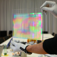
An important milestone has been reached for the Gaia Radial Velocity Spectrometer (RVS): the full-size demonstrator model of the RVS grating - a key component responsible for the dispersion of the light into constituent wavelengths - has been built by industry and was delivered to ESA last month.
 |
|
Figure 1. Demonstrator model of the RVS grating. |
The RVS is one of the three integrated instrument functions of the Gaia payload. Part of the light collected by the large telescopes on the Gaia spacecraft will pass though the RVS to perform high-resolution spectroscopic observations of stars that pass through the field-of-view. The stellar velocities derived from these data, in combination with the accurate position measurements that will also be acquired by the Gaia payload, will create a detailed three-dimensional spatial map - 6-dimensional phase-space map - of our Galaxy.
Blazed gratings
To perform the spectroscopic observations the RVS will have a blazed transmission grating in the optical path for dispersion of the light. In general, transmission gratings have numerous parallel grooves on their surface which cause light passing through the grating to emerge in an interference pattern. At specific angles the light interferes constructively and these peaks are referred to as orders. Within each order light is also dispersed by wavelength.
Blazed transmission gratings have specifically designed groove cross-sections that cause most of the incident light to be transmitted into a selected order of the interference pattern. This is expressed in the efficiency, which is the ratio of the amount of light dispersed into the desired order (m=+1 for RVS) to the amount of incident light.
The common groove cross-section for blazed gratings is a saw-tooth pattern in the surface layer of the grating. But the RVS grating is made with a challenging technique to realise a unique groove cross-section. This was needed to be able to meet all requirements for the RVS: the resolution for separating the constituent wavelengths must be λ/Δλ=
Unique surface structure of the RVS grating
 |
|
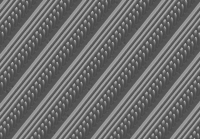
Figure 2. Electron microscope image of the grating's surface texture revealing the regular pattern of discrete patches. |
The blazed transmission grating developed by IOF for the RVS is a 9 mm thick fused silica plate, of which the top surface layer has been carefully etched with an accuracy of about 20 nm in depth to form the grating grooves (Figure 2).
Rather than the regular saw-tooth pattern for the grating cross-section, the RVS grating has a unique sequence of discrete patches with a block shape. The pattern is a repeated set of five blocks of increasingly smaller widths. The spacing between the patches as well as the width of each individual patch is smaller than the wavelengths that the RVS will study (which lie in the narrow near-infrared band between 847-874 nm).
This means that at these wavelengths the light does not "see" the individual patches, but rather the integrated profile of the patches. The net effect is the same as for a regular saw-tooth pattern, but the discrete patches allow for all the optical requirements to be met, including the very high efficiency.
The development of the RVS grating by IOF was tackled in two steps. In June 2008 a small-scale version was made to prove that the required pattern of sub-wavelength scale patches (called the binary index modulation structure) could be made using a challenging technique. The full-size demonstrator model was successfully created a few months later and delivered to ESA on 10 December 2008. This success now clears the way for developing the actual flight model of the blazed transmission grating that will fly onboard Gaia early in the next decade.