Instruments
Baseline instrument concept
| NOTE: In March 2011 ESA announced a new way forward for the L-class candidate missions: IXO, EJSM-Laplace and LISA. At this time the IXO concept ceased to be a candidate and ESA, along with the scientific community, is now investigating to what extent a European-led mission could preserve the original science case of IXO. The new study is called ATHENA (Advanced Telescope for High ENergy Astrophysics). |
In order to fulfil the IXO science requirements the following baseline instrument complement has been adopted:
- Wide Field Imager (WFI)
- Hard X-ray Imager (HXI)
- X-ray Microcalorimeter Spectrometer (XMS)
- High Time Resolution Spectrometer (HTRS)
- X-ray Polarimeter (X-POL)
- X-ray Grating Spectrometer (XGS)
The baseline instrument payload (see table below) is used during mission studies to scope the key elements of the mission and to ensure that the scientific requirements of the mission can be achieved. An Announcement of Opportunity will be issued at a later date inviting the community to propose specific instruments for the observatory.
 | |
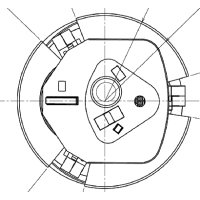 |
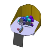
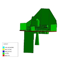
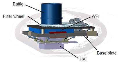
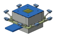
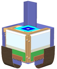
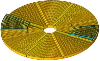
Above: Schematic illustration of the location of the instruments. Left: Top view of the IXO instrument module; Below (left): assembly view of the IXO instrument module; Below (right): geometrical mathematical module. Credit: ESA |
 |
 |
|
Summary of the baseline instrument payload | |||
| WFI | HXI | XMS | |
| Detector type | Si APS (DEPFET) | CdTe + Si strip detectors | Micro-calorimeter / TES |
| Operating temp | 210 K | 253 K | 50 mK |
| Cooling | Radiator (+Peltier) | Radiator | Closed cycle coolers / ADR |
| Detector size (mm) | 102.4 × 102.4 | 70 × 70 | 31.2 × 31.2 |
| Energy Range (keV) | 0.1 - 15 | 10 - 40 | 0.2 - 6 |
| Energy resolution (FWHM) | 70 eV |
1 keV |
3 eV |
| Pixel size (µm) | 100 | 220 | 300 (& 600) |
| No. pixels in one direction | 1024 | 320 strips | 40 (+ 32) |
| Field of View (arcmin²) | 18 | 12 | 2 (& 5.3) |
| Unvignetted FoV (arcmin*) |
18 (diam) TBD | 12 (diam) TBD | 5.3 (diam) |
| *: assuming a circular field of view | |||
|
Summary of the baseline instrument payload (continued) | |||
| HTRS | X-POL | XGS | |
| Detector type | Silicon Drift Diodes (SSD) | Gas Pixel Detector | CCD |
| Operating temp | 253 K | 290 K | 170 K |
| Cooling | Radiator | None | Radiator |
| Detector size (mm) | 16.8 (Hexagonal) | 16 × 16 | 741 × 28.8 |
| Energy Range (keV) | 0.5 - 20 | 2 - 10 | 0.3 -1 |
| Energy resolution (FWHM) | <200 eV |
1200 eV |
E/ΔE = 1250 |
| Pixel size (µm) | 2400 | 50 | 18 |
| No. pixels in one direction | 7 | 320 | 40960 |
| Field of View (arcmin² ) | 2.8 (Hexagonal) | 2.8 | n/a |
| Unvignetted FoV (arcmin*) | 2.8 (diam) | 2.8 | n/a |
| *: assuming a circular field of view | |||
Wide-Field Imager (WFI)
| NOTE: In March 2011 ESA announced a new way forward for the L-class candidate missions: IXO, EJSM-Laplace and LISA. At this time the IXO concept ceased to be a candidate and ESA, along with the scientific community, is now investigating to what extent a European-led mission could preserve the original science case of IXO. The new study is called ATHENA (Advanced Telescope for High ENergy Astrophysics). |
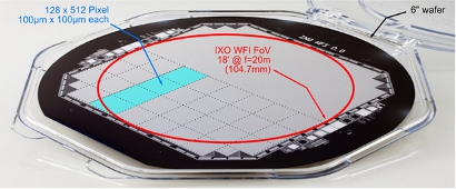
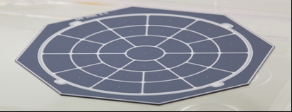
The IXO Wide Field Imager (WFI) is an imaging X-ray spectrometer with a large field of view (18x18 arcmin²). The purpose of the WFI is to provide images in the energy band 0.1 - 15 keV, simultaneously with spectrally and time resolved photon counting.
 | |
 | |
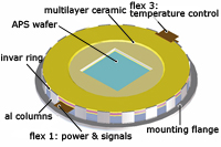 |
Top: Schematic figure of the WFI camera assembly. Credit: WFI team |
Technical Status
The WFI is based on well-developed technology which is currently being space qualified. A WFI-type instrument will be flown on ESA's BepiColombo spacecraft – the flight model is currently under construction – and on the French/Italian Simbol-X spacecraft. Future evolution of the WFI concept requires the development of a specific design compatible with the IXO payload configuration and to demonstrate that a full wafer sensor can be used. In addition, further work is planned for the proximity electronics, in particular in developing faster ASICs.
Hard X-ray Imager
| NOTE: In March 2011 ESA announced a new way forward for the L-class candidate missions: IXO, EJSM-Laplace and LISA. At this time the IXO concept ceased to be a candidate and ESA, along with the scientific community, is now investigating to what extent a European-led mission could preserve the original science case of IXO. The new study is called ATHENA (Advanced Telescope for High ENergy Astrophysics). |
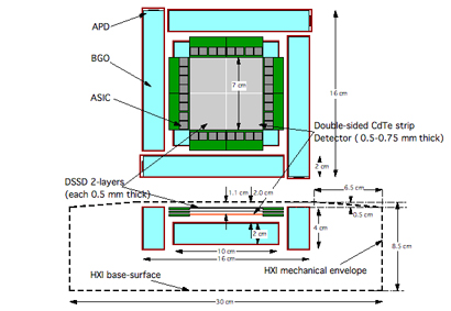
The Hard X-ray Imager (HXI) is mounted beneath the WFI. It will extend the energy coverage up to 40 keV and enable simultaneous observations with both instruments. HXI should have an energy resolution better than 1 keV (FWHM) at 40 keV and cover a FOV of 12 × 12 arcmin².
The HXI detector is made up of three layers, 2-Silicon (Si) and 1 Cadmium Telluride (CdTe) detector, sitting back from the WFI plane by about 20, 25 and 30 mm, respectively. The 30 mm offset of the CdTe detector from the focal plane causes a PSF broadening of about 15 arcsec, assuming a mirror effective diameter of 1 m at 30 keV.
A consequence of the co-location of the two instruments is that they share an optical axis, and the same baffle structure, with heavy metal sheets added for hard X-ray coverage. A thermal shield will be required between the WFI and HXI since they operate at different temperatures. The HXI cooling design, mechanical structure and electrical interfaces are all independent from the WFI, so that both instruments can be operated separately.
 | |
|
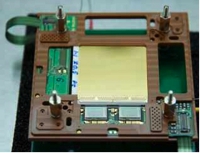
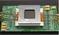
Above: Geometry of the detectors in the HXI focal plane. Credit: ESA Below: (left) The HXI detector assembly, attached to the WFI, and (right) a double-strip CdTe detector. Credit: HFI team | |
 |
 |
The high mass absorption coefficient of Cadmium Telluride (CdTe) allows for the efficient detection of hard X-ray photons. In order to obtain high spatial resolution that matches the angular resolution of IXO telescope, and to cover the wide FOV, the detectors will consist of Double-sided Strip CdTe detector (DS-CdTe detector). A detector with a thickness of 0.5 mm provides nearly 100 per cent detection efficiency for 40 keV hard X-ray photons. To suppress background, an active BGO anticoincidence shield is deployed around the imager. In addition, two layers of Double-sided Si Strip Detector (DSSD), with dimensions the same to those of the CdTe detector (i.e. 7×7 cm² wide and with a thickness of 0.5 mm) will be mounted above the CdTe and serve as particle background detectors as well as detectors of X-ray signals in the 10-30 keV band.
Technical status
The HXI is based on proven technology – a similar instrument has been developed for the ASTRO-H spacecraft. One aspect that will require investigation is the design of an optimum engineering solution for mounting the HXI behind the WFI.
X-ray Microcalorimeter Spectrometer (XMS)
| NOTE: In March 2011 ESA announced a new way forward for the L-class candidate missions: IXO, EJSM-Laplace and LISA. At this time the IXO concept ceased to be a candidate and ESA, along with the scientific community, is now investigating to what extent a European-led mission could preserve the original science case of IXO. The new study is called ATHENA (Advanced Telescope for High ENergy Astrophysics). |
The purpose of the XMS is to provide spectra with a resolving power E/δE of several hundred in the energy range 0.2 – 6 keV, simultaneously with images of a modest (2 arcmin) field of view. This is achieved by time resolved photon counting.
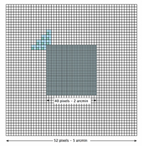
The XMS is based on an array of micro-calorimeters (see Figure below) which will be configured as an inner array (40x40 pixels on a pitch of 300 μm) providing high energy resolution (2 eV FWHM) and an outer array (of larger pixels on a 600 μm pitch) with lower energy resolution (<10 eV FWHM).
 |
 |
 |
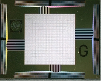
Above left: CIS detector array arrangement. Credit: ESA Above right: Prototype 32×32 detector array. Credit: XMS team Left: Diagram of the focal plane assembly. Credit: XMS team. |
Each pixel in the array consists of a Bi/Cu X-ray absorber of typically 300 × 300 μm² size and 7 μm thickness of which the temperature is read-out by a normal-to-superconducting phase transition thermometer with a critical temperature Tc ≈ 100 mK, usually referred to as a Transition-Edge-Sensor (TES). The absorber-thermometer combination is weakly coupled to the 50 mK base temperature of the cryostat by means of a Si3N4 membrane. Each pixel in the array is voltage-biased thereby raising the device temperature into the transition at about 100 mK. Subsequently the current signals are amplified by cryogenic SQUID-amplifiers (50 mK – 2.5 K), which are linearized by room temperature feedback electronics.
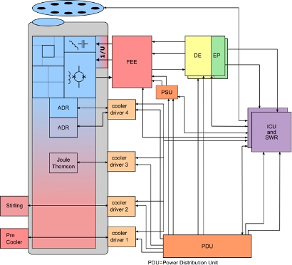
The detector operates at 50 mK and will be cooled to this temperature by a multistage adiabatic demagnetization refrigerator (ADR) operating in series with a mechanical cryo-cooler. No expendable cryogens are foreseen for the XMS.
 |
|
The overall instrument architecture. Credit: XMS team |
Technical Status
The XMS is based on TES for which there has been extensive development work both in Europe and the US. Institutes on both sides of the Atlantic have demonstrated significant progress in developing sensors that can achieve the energy resolution required for IXO. While the basic principles have been clearly demonstrated the next step is to show that large arrays can be fabricated which maintain the performance requirements. Another key technology which needs further development is the multiplexing of the sensor’s signals to minimize the heat load caused by thermal conduction through the harness to the cold finger.
Additional development remains to qualify a cryo-chain to achieve the detector operating temperature of 50 mK. All of the individual elements that are needed to develop the optimum cryo-chain for the IXO payload configuration already exist.
(Editor's Note: During an early study phase of IXO the XMS was known as the CIS (Cryogenic Imaging Spectrograph). )
High Time Resolution Spectroscopy (HTRS)
| NOTE: In March 2011 ESA announced a new way forward for the L-class candidate missions: IXO, EJSM-Laplace and LISA. At this time the IXO concept ceased to be a candidate and ESA, along with the scientific community, is now investigating to what extent a European-led mission could preserve the original science case of IXO. The new study is called ATHENA (Advanced Telescope for High ENergy Astrophysics). |
The purpose of the HTRS is to provide spectra with resolving power E/δE of 5-50 in the energy range 0.5 to 10keV, at very high time resolution (10μs) and with very high count rate capability (up to 2M counts per second).
The HTRS is based around an array of silicon drift diodes (SDD). The SDD is a completely depleted volume of silicon in which an arrangement of increasingly negatively biased rings drive the electrons generated by the impact of ionising radiation towards a small readout node in the centre of the device. The time needed for the electrons to drift is much less than 1μs.
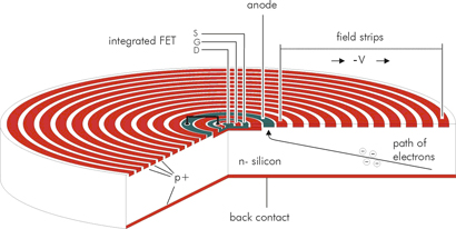 |
|
Principle of a single drift diode X-ray spectrometer. |
The main advantage of SDDs over conventional PIN diodes is their small physical size and consequently the small capacitance of the anode, which translates to a capability to handle very high count rates simultaneously with good energy resolution. To take full advantage of the small capacitance, the first transistor of the amplifying electronics is integrated onto the detector chip. The stray capacitance of the interconnection between the detector and amplifier is thus minimized and, furthermore, the system becomes practically insensitive to mechanical vibrations and electronic pickup.
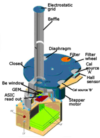
The HTRS will rely on an array of 37 hexagonal SDD pixels patterned on a single substrate. The sensor will be placed slightly out-of-focus in order to spread the photons as evenly as possible over all pixels and thus increase the overall count rate capability of the instrument. As such the instrument will not be truly "imaging".
 |
 |
|
Top: HTRS camera assembly; Bottom: Detector prototype. |
Technical Status
The HTRS is based on the WFI detector technology but using fewer and larger pixels. No fundamental technology development is required. Future work will involve the development of fast electronics.
X-ray Polarimeter (XPOL)
| NOTE: In March 2011 ESA announced a new way forward for the L-class candidate missions: IXO, EJSM-Laplace and LISA. At this time the IXO concept ceased to be a candidate and ESA, along with the scientific community, is now investigating to what extent a European-led mission could preserve the original science case of IXO. The new study is called ATHENA (Advanced Telescope for High ENergy Astrophysics). |
The purpose of the XPOL is to provide, in the energy range 2 – 10 keV, polarization measurements simultaneously with angular measurement (5 arcsec), spectral measurements (E/δ E of ~5 @ 6 keV) and timing at few μs level.
The XPOL derives from a Gas Pixel Detector - an advanced evolution of the Micropattern Gas Chamber where the multi-anode read out is fully pixellated. It is based on a gas cell with a thin entrance window and a detection/drift gap where the X-ray photon is absorbed with the ejection of a photoelectron that produces an ionization pattern in the gas (track).
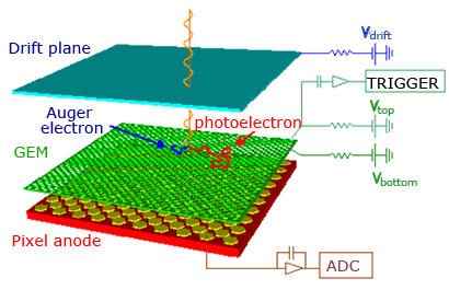 |
|
Sketch of the XPOL detection principle. |
The track is drifted by a parallel electric field to a Gas Electron Multiplier (GEM) that multiplies the track without modifying the shape. At a short distance a collection anode plane is covered by metal pads with a high filling factor distributed on a hexagonal pattern. Each pad has its own independent electronic chain to detect the charge collected from the conversion gap.
The image of the track is analysed to reconstruct the point of impact and the original direction of the photoelectron. The reconstructed point of impact instead of the charge centroid gives this detector an imaging resolution down to 150 μm FWHM, largely oversampling the PSF. An additional blurring of the order of 2 mm (diameter) should be accounted for due to the absorption of photons from an inclined beam at different heights in the gas.
The linear polarization is determined from the angular distribution of the photoelectron tracks.
 Above: A possible configuration for XPOL. Credit: ESA |
|
The gas cell will comprise a self-triggering CMOS analog chip. The top metal layer of the CMOS pixel array is patterned in a matrix of 105600 hexagonal pixels with a 50 μm pitch. Each pixel is directly connected to the underlying full electronics chain which has been realized in the remaining five metal and single poly-silicon layers of a 0.18 μm VLSI technology. The noise of each chain is 50 e- rms only. With the moderate gain of 500, single electrons produced in the gas cell can be detected.
The system has the capability to auto-trigger and only data included in a window around the pixels that triggered are fetched for A/D conversion. Therefore notwithstanding the large number of pixels, only sub-frames of 400 to 600 pixels, completely including the track, are extracted in real time for each event.
Technical status
Gas Pixel Detectors, on which the XPOL is based, have been successfully fabricated and future developments focus on improving the performance and on space qualifying the technology.
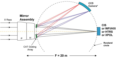
X-ray Grating Spectrometer (XGS)
| NOTE: In March 2011 ESA announced a new way forward for the L-class candidate missions: IXO, EJSM-Laplace and LISA. At this time the IXO concept ceased to be a candidate and ESA, along with the scientific community, is now investigating to what extent a European-led mission could preserve the original science case of IXO. The new study is called ATHENA (Advanced Telescope for High ENergy Astrophysics). |
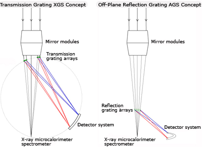
The XGS will be a dispersive spectrometer with an effective area of more than 1000 cm² from 0.3 to 1 keV. It will have a spectral resolving power of about 1250 over the full band. Two grating arrays will be mounted behind the optics. Both arrays will use the same CCD readout.
Two grating technologies are under investigation: a 'critical angle transmission' (CAT) grating, and an off-plane reflection grating.
 | |
|
Above: Schematic diagram of the transmission grating and off-axis reflection grating concepts. | |
 | |
 |
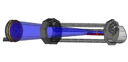
Above: The tower configuration for the off-plane configuration. Left: Camera assembly for the off-plane configuration. |
 |
 |
|
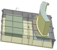
Schematic figures showing the (left) camera assembly for the transmission grating optics and (right) grating arrays behind the Silicon Pore Optics. Credit: CAT-XGS team | |
The CCD detector array, comprising 10 CCDs in a 780 mm long array, would be read out at 10Hz. Back-illuminated CCDs with high QE below 1 keV and thin optical blocking filters are foreseen. Energy resolution of 160 eV is required to separate the spatially overlapping spectral orders.
Technical Status
The XGS will employ standard CCD technology similar to that used for XMM-Newton. No specific technology development for the camera is envisaged for IXO.
The CAT gratings are constructed from very thin plates: 100 nm thin with 100 nm spacing. The large scale construction of these gratings has yet to be demonstrated.