NIRSpec – the Near-Infrared Spectrograph on JWST
The primary science goal for NIRSpec is to enable large spectroscopic surveys of astronomical objects with a particular focus on the study of distant galaxies. It has driven the design of this multi-object spectrograph, which is capable of measuring the spectra of up to 200 objects simultaneously in a 3.4 arcminute × 3.6 arcminute field of view. NIRSpec also includes five fixed slits and an integral field unit that provide spectra of point-like sources and of extended objects, respectively. Six gratings provide high-resolution (λ/Δλ=R=1400-3600) and medium-resolution (R=500-1300) spectroscopy over the wavelength range of 0.7 µm - 5 µm, while a prism yields lower-resolution (R=30-300) spectroscopy over the range 0.6 µm - 5 µm.
NIRSpec has been built by European industry to ESA's specifications and managed by the ESA JWST Project at ESTEC, the Netherlands. The prime contractor is Airbus Defence and Space in Ottobrunn, Germany. The NIRSpec detector and micro-shutter array subsystems are provided by NASA's Goddard Space Flight Center (GSFC).
 |
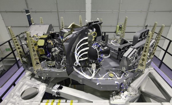
| JWST's Near InfraRed Spectrograph (NIRSpec). Credit: Airbus Defence and Space GmbH |
Microshutter Array – key to multi-object spectrography capability
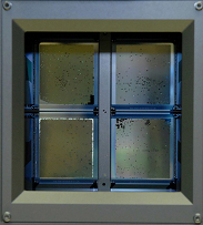
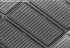
One of the defining, and pioneering, features of NIRSpec is its ability to record the spectra of up to 200 objects at the same time. This multi-object spectrography capability is made possible by the use of an innovative micromechanical slit selection device. The first stage of the optical train (the Coupling & Fore Optics) re-images the NIRSpec field of view onto a Microshutter Array (MSA; provided by NASA) consisting of just under a quarter of a million individually controlled microshutters. By programming the MSA to only open the shutters that coincide with the pre-selected objects of interest, light from these objects is then isolated and allowed to enter the spectroscopic stage of the instrument. Since each shutter is individually controlled, a number of slit patterns can be configured using the MSA.
Fixed slits – providing high contrast spectra of sources and a key to the study of exoplanets
NIRSpec will also be able to carry out single-object, high-contrast spectroscopy using a set of five fixed slits. One of these slits is a square aperture of 1.6 arcsec × 1.6 arcsec that will be used to obtain spectra of transiting exoplanets.
The fixed-slit spectra can be taken independently to, and simultaneously with, the spectra taken with the Microshutter Array or the Integral-Field Unit. This is because they are imaged on different areas of NIRSpec detectors.
Integral Field Unit - providing spectra of extended objects
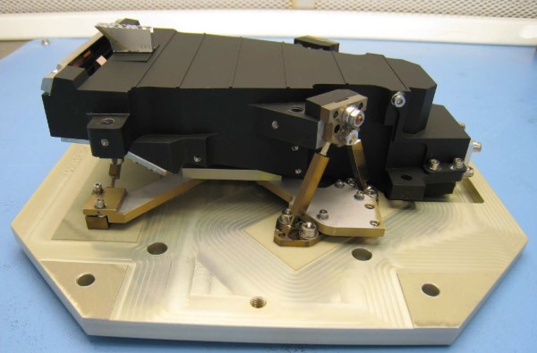
NIRSpec also harbors an Integral-Field Unit (IFU) with a field of view of 3 arcsec × 3 arcsec that will be split into 900 spectra, each corresponding to a tiny spatial element of size 0.1 arcsec × 0.1 arcsec. Mounted just behind the microshutter arrays, the IFU uses the so-called image-slicing technique to cut the image of the object into 30 slices. Each slice will then give rise to 30 contiguous spectra on the detectors.
 |
| The NIRSpec IFU flight model. Credit: SSTL |
Dispersive elements - prisms and gratings for low to high spectral resolution
The first part of the spectrographic stage of NIRSpec's optical train (the Collimator and Grating Wheel) serves to separate the light passing through the microshutters, slits or IFU into its component wavelengths (spectra) by means of a prism or one of six diffraction gratings which constitute the set of NIRSpec dispersive elements. When using diffraction gratings as dispersive elements, three separate gratings are employed in combination with specific filters in order to avoid the overlapping of spectra caused by different grating orders. The three gratings span four partially overlapping bands (0.7 µm – 1.27 µm; 0.97 µm – 1.84 µm; 1.66 µm – 3.07 µm; 2.87 µm – 5.10 µm) covering the total spectral range in four separate exposures.
Depending on the source brightness and the astrophysical problem at hand, the prism and gratings allow the user to disperse the target light by different amounts, and separate adjacent wavelengths to a relative accuracy (or spectral resolution) of R = 30-300 (prism), 500-1300 (medium-resolution gratings), or 1400-3600 (high-resolution gratings).
State-of-the-art detectors
The detectors mounted onto the NIRSpec focal plane are state-of-the-art and are designed to meet the challenging requirements of (i) extraordinary sensitivity - to record the faint signals from the farthest galaxies - and (ii) large number of pixels, matching the 3.4 arcmin × 3.6 arcmin-wide field of view - to efficiently survey the sky. Their detector quantum efficiency is above 0.7-0.8 electron-per-photon throughout the 0.6 µm to 5.0 µm wavelength band; their pixel dark current is less than 0.01 electron per second; the total detector noise for a 1000-second integration is only 6 electrons.
The detector focal plane consists of two HgCdTe sensor chip assemblies. Each chip is a 2D array of 2048 × 2048 pixels, 18 micron pitch, hybridised onto a dedicated Read-Out-Integrated Circuit. Two Application Specific Integrated Circuits (ASICs) control the detector chips and digitise their extremely low analogue signals. Each pixel can be individually addressed and read out in a non-destructive way. A Molybdenum structure protects the detectors from stray light and radiation. Mounted onto the back of the camera optics, via three M-flexure mounts (120 degrees apart to optimise their mechanical stability), the detectors are cooled by a dedicated radiator and kept at an operating temperature of about -233 °C (~ 40 K) with an accuracy of about 20 thousandths of a degree. In order to meet the extremely demanding thermal requirements, the combined detector and ASIC heat dissipation must be less than 44 mW, a very challenging value.
A highly modular optical design
The optical design is based on an all reflective system comprising fourteen mirrors (two mirrors made of Zerodur and twelve of Silicon Carbide), all coated with a reflective silver layer. The quality of the optical train is state-of-the-art both in terms of reflectivity values, which are above 97% per mirror, and in terms of the wave-front error (optical quality): the latter is only 180 nm RMS in total, equivalent to a diffraction limited performance of about 2.5 µm, when considering also the wave-front error contribution of the JWST telescope.
 |
| Optical elements of the NIRSpec instrument. (Click on the image for an expanded description of the optical design.) Credit: Airbus Defence and Space GmbH |
The NIRSpec optical design is a highly modular system, featuring 3 three-mirror-anastigmat optics assemblies, and six main opto-mechanical systems, which can be integrated, aligned and tested independently.
The three optics assemblies are:
Coupling & Fore optics, which re-image and demagnify, with very limited optical distortions, the huge 3.4 arcmin × 3.6 arcmin fraction of the curved telescope focal surface allocated to NIRSpec onto its first smaller image plane, where the Microshutter Array lies. The Coupling & Fore optics also create a (nearly) collimated beam where the filter wheel is positioned, in this way minimising the chromatic aberrations;
Collimator optics, which transform the divergent beam into a collimated one impinging onto the grating wheel mechanism where the dispersive optical elements are housed, in this way minimising the optical aberrations.
Camera optics, which focus the spectra, and at the same time further de-magnify them, onto the detector focal plane with an optimum plate scale (100 milliarcsec per 18 micron pixel).
The six opto-mechanical elements are: a Microshutter Assembly (described above), a detector assembly (described above), a filter wheel mechanism, a refocusing mechanism, a grating wheel mechanism and a calibration sphere.
The refocusing mechanism compensates for possible telescope focal length changes during its lifetime and properly re-images its focal surface onto the Microshutter Assembly.
The filter wheel mechanism, houses a set of two broadband filters, four long-pass filters, one clear aperture for imaging purposes and a pupil reference/calibration mirror: the former serves for alignment purposes while the latter is used during periods of instrument self-calibration.
The grating wheel mechanism houses one calcium fluoride (CaF2), low resolution (R=30-300) double-pass prism; three medium resolution gratings (R=500-1300) and three high resolution gratings (R=1400-3600), and an imaging Silver-coated mirror for target acquisition purposes. The gratings grooves are ruled onto a gold-coated Zerodur substrate, a glass ceramic with an extremely low coefficient of thermal expansion.
A calibration sphere, or internal calibration assembly, will be used to quantify the effects of spectral, radiometric and geometric distortions. The assembly consists of an integrating sphere fed by 11 lamps with broadband and spectral line filters providing both continuum and spectroscopic line illumination to the instrument. The main purpose of the integrating sphere is to provide a homogeneous beam at its exit aperture located in a pupil plane. By means of six mirrors, three of which belong to the nominal optical train, the assembly's exit aperture is re-imaged onto the MSA plane in a telecentric way.
Super-stable materials
The optical assembly, which houses all the opto-mechanical assemblies, is at the heart of the instrument. The selection of the construction material for this structure was driven by the following challenges:
-
The same material must be used for both structural parts and optical elements in order to achieve an 'athermal' design, minimising any distortion.
-
The material had to have an extremely low coefficient of thermal expansion and good thermal conductance to minimise any distortion.
-
The thermal expansion mismatch with the NASA-provided payload supporting structure, built from Carbon Fibre, had to be reduced to almost zero.
-
The Young's Modulus must be high and the density low in order to obtain a light yet rigid design.
The strength of the material had to be high enough to cope with the design and test loads. -
It must be polished to a fraction of a micron in order to attain the quality demanded by the optical train.
Silicon Carbide, a novel ceramic material, with very high stiffness-to-mass ratio and a very high thermal stability met all these challenges and so has been used for the mirrors and the structural parts of the instrument.
As with all infrared instruments NIRSpec will operate at cryogenic temperatures (~ -233 °C; ~40 K). Most of the opto-mechnical mechanisms have been designed to meet an extremely stringent power dissipation constraint, which must not exceed 69 mW in order to maintain the thermo-mechanical stability of the instrument, an important characteristic of this ground-breaking spectrograph.
NIRSpec is built by European industry to ESA's specifications and managed by the ESA JWST Project at ESTEC, the Netherlands. The prime contractor is Airbus Defence and Space GmbH in Ottobrunn, Germany. The NIRSpec detector and MSA subsystems are provided by NASA's Goddard Space Flight Center (GSFC).


