Instruments
Summary
What will all the instruments do?
Multinational teams of scientists and engineers will conduct ten different investigations coordinated by a Science and Technology Operations Centre. Instrument teams are led by principal investigators from Finland, Germany, Italy, Switzerland and the United Kingdom. All ESA member countries are taking part, providing coinvestigators for various experiments.
Testing new techniques
EPDP and SPEDE. Designers of future solar-electric spacecraft want to know how SMART-1's ion engine performs, what side effects it has, and whether the spacecraft interacts with natural electric and magnetic phenomena in the space around it. Possible problems include deflection of the ion engine's drive direction, erosion of surfaces, short-circuits by sparks, interference with radio signals, and accumulating dust. The main onboard instruments monitoring these effects are EPDP and SPEDE.
KaTE and RSIS. Small changes in SMART-1's motion will reveal the precise drive delivered by the ion engine. Similarly to police radars used to catch speeding motorists, RSIS will employ the Doppler effect to see how the speed alters the wavelength of radio pulses. It will use the very short radio waves of KaTE. The primary purpose of KaTE is to demonstrate the next generation of radio links between the Earth and far-flung spacecraft. Microwaves of the Ka band, around 9 millimetres in wavelength, can be focused into relatively narrow beams by the small dish antennas available on spacecraft.
Laser Link is another communications experiment. ESA already has laser links with telecom satellites from an optical ground station on Tenerife in Spain's Canary Islands. Aiming the beam becomes much more difficult if, like SMART-1, the spacecraft is far away and moving rapidly. The hope is that the onboard camera AMIE will see Tenerife illuminated with laser light.
OBAN. Future spacecraft will be more self-reliant in guiding themselves along predefined paths towards distant destinations. OBAN will evaluate a computer technique for on-board autonomous navigation. It will use the bearings of stars seen by SMART-1's star trackers, and the Earth, Moon and possibly asteroids seen by the AMIE camera.
Observing the Moon and the Sun
AMIE, SIR and D-CIXS. Different kinds of visible and invisible light coming from the lunar surface will provide clues about its chemical composition and geological history. The ultracompact electronic camera, AMIE, will survey the terrain using visible and near-infrared light. An infrared spectrometer, SIR, will chart the Moon's minerals. An X-ray spectrometer, D-CIXS, will identify key chemical elements in the lunar surface.
XSM. The D-CIXS measurements can be confusing because of variations in solar X-ray emissions, which depend on how stormy the Sun is on that day. For this reason, SMART-1 monitors the solar X-rays with its XSM instrument. XSM will also make its own independent study of solar variability.
SPEDE. Similarly to a ship at sea, the Moon leaves a wake in the solar wind - the non-stop stream of charged particles and associated magnetic fields coming from the Sun. The SPEDE electrical experiment will observe this effect from close by.
RSIS. Using the KaTE microwave system and the AMIE camera, the RSIS radio experiment will demonstrate a new way of measuring the rotations of planets and their moons. It should be able to detect a well-known nodding of the Moon, which slightly tilts first its north pole and then its south pole, towards the Earth.
These instruments and techniques that will be tested when SMART-1 examines the Moon will later help ESA's BepiColombo spacecraft to investigate the planet Mercury.
Onboard Autonomous Navigation (OBAN)
In recent years, spacecraft destined to explore the Solar System have become more compact and complex. One of the key elements in the general trend of 'Faster, cheaper, better' is the principle of autonomous operations.
When missions to other planets often hundreds of millions of kilometres away take years of precise navigation to be successful, the more a spacecraft can take care of itself, the easier it is for the mission teams back on Earth.
One of the important components of onboard autonomous operations is navigation, the determination of a spacecraft's trajectory and the computation of the corrections required to reach a target.
Teams managing spacecraft operations are today often mobilised for months monitoring a spacecraft as it progresses. A course manoeuvre can be preceded by weeks of intensive calculations at ground level. Such operations can be costly.
To date, the only interplanetary mission to feature an onboard autonomous navigation system is the NASA asteroid fly-by probe, Deep Space 1 (DS1), launched in October 1998. Following in its steps, SMART-1 will be contributing to a European capability in this field with OBAN, an experiment on OnBoard Autonomous Navigation for interplanetary missions.
OBAN is part of a study on 'Autonomous Onboard Navigation for Interplanetary Missions', of ESA's Technology and Research Programme. It is being managed by Finn Ankersen, Guidance, Navigation and Control analyst at ESTEC, Noordwijk, the Netherlands, in cooperation with the European Space Operations Centre (J. Fertig), ESOC in Darmstadt, Germany.
Some basic geometry
SMART-1 will not itself be relying on OBAN for its own guidance and navigation which will be managed in a conventional way from the SMART-1 Mission Operations Centre at ESOC. The OBAN experiment will function in what is termed an 'open loop', obtaining all the data an autonomous navigation system would require, but instead of being processed onboard, this information will be sent back to be processed on Earth.
The experiment will involve the spacecraft looking at certain celestial objects or 'beacons', taking images of them with the AMIE camera. These time-tagged pictures, together with information from SMART-1's Attitude and Control Systems will allow the OBAN ground system to determine the lines of sight to the beacons, and calculate the precise trajectory. Subsequently all the parameters that would be required to carry out a correction in the spacecraft's course can be obtained. The picture analysis algorithms and computations will be extremely complex, but the principles of the experiment are those of elemental triangulation geometry.
"Although we will have carried out simulations before the launch with synthetic images, the challenge of the OBAN experiment will be to get the algorithms to work properly using real images obtained in flight," says Finn Ankersen.
|
|
|
Schematic representation of OBAN (inset Finn Ankersen) |
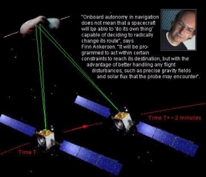
Onboard autonomy in navigation does not mean that a spacecraft will be able to "do its own thing", capable of deciding to radically change its route. It will be programmed to act within certain constraints to reach its destination, but with the advantage of better handling any flight disturbances, such as precise gravity fields and solar flux that may be encountered.
Autonomous navigation will never eliminate the need for ground operations, if only to receive the science data and because spacecraft housekeeping will always be necessary. But onboard autonomy will eventually allow less frequent contact periods and hence considerably decrease mission costs.
The OBAN experiment will be conducted several times whilst SMART-1 spirals out from Earth to reach the Moon. Since the required pictures will mean slewing the spacecraft to point towards one beacon body, then a second, the experiment will take place when the solar propulsion is not working. The beacons to be used will be the Earth, the Moon and perhaps asteroids.
With the OBAN experiment on SMART-1, European onboard autonomous navigation will be passing from a preliminary study to an experimental phase. Its full operational use on future missions is not far off. ESA's projected mission to Mercury may be too far advanced to benefit, but it is reasonable to believe that all interplanetary missions in the future will feature such a system.
EPDP & SPEDE
Monitoring the side effects of electric propulsion
 |
|
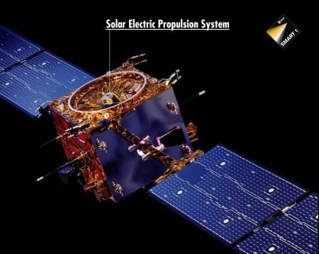
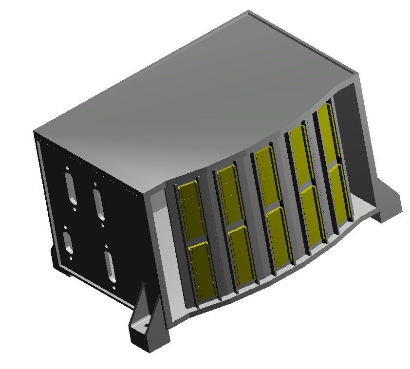
Some of the SMART-1 instruments will monitor the effects of the solar electric propulsion system. |
The main effects of the operation of a Hall thruster are physical, mechanical, thermal and electrical. The plasma can cause erosion and redeposition of eroded material on surrounding surfaces. The beam impact on spacecraft surfaces can produce torque and variations in the thrust vector. Surface temperatures can rise. Surface potentials may change and electromagnetic effects can be induced by the on-off operation of the thruster and produce radio-frequency interference to, for instance, the spacecraft antennae. Ground measurements of such effects in vacuum chambers do not fully reflect space conditions and the true spacecraft geometry cannot be simulated. Real spaceflight data are therefore essential.
EPDP: monitoring solar electric propulsion
The Electric Propulsion Diagnostic Package (EPDP) will monitor these effects. The package consists of a number of sensors, mounted on the bottom panel of the spacecraft, approximately 80 cm from the thruster. It represents approximately 2 kg of instrumentation and electronics. A Retarding Potential Analyser will measure the ion energy and current density distribution. The ions that will be measured are those of low energy mainly responsible for the backflow contamination. With the resulting data, designers of future space science missions will be able to optimise the position of thrusters and payload instruments for spacecraft of different shapes.
A Langmuir Probe will measure the plasma potential and the electron density and temperature. It will give information on the plasma conditions at one side of the spacecraft, whilst another probe will give similar information on the opposite side. Using single point measurements, 3D representations of the environment will be possible.
EPDP also includes a solar cell, placed away from the spacecraft's solar array, and a Quartz-Crystal Micro-balance which will both be used as deposition material sensors, providing real data on the extent of contamination.
Complimentary information on the consequences of the solar electric propulsion will be obtained notably from the spacecraft's Attitude Control System, from the telemetry of the onboard antennae, house keeping data from the solar arrays, from the operation of the spacecraft's hydrazine thrusters and from disturbances to the payload data that is obtained when the electric propulsion is functionning.
The main contractor for EPDP is LABEN/PROEL (Florence, Italy) whose Giovanni Noci is the EPDP technology investigator. Scientific co-ordinator is Josi Gonzales, from ESA's Electric Propulsion Unit at ESTEC, Noordwijk, the Netherlands.
SPEDE: Piggyback plasma science
The EPDP package also supports the science investigations of the Spacecraft Potential, Electron and Dust Experiment (SPEDE - 'speedy' for which A. Malkki, from the Finnish Meteorological Institute (FMI), Helsinki, is the principal investigator.
 |
|
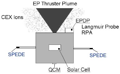
Diagram indicating location of EPDP/SPEDE detectors around the thruster. |
The Geophysical Research unit at FMI does research in the fields of space plasma physics, geomagnetism, aeronomy, and planetary research. It has contributed to the SOHO satellite providing (together with Service Aeronomie, Paris, France) the SWAN instrument which since 1996 has been observing solar Lyman-alpha radiation, the heliopause signatures and solar corona, and which has monitored several comets.
SPEDE represents but 800 g of equipment. The experiment is built jointly by investigators from FMI (Helsinki, Finland), ESA/SSD (Noordwijk, the Netherlands), IRFU (Uppsala, Sweden) and KTH (Stockholm, Sweden).
SPEDE consists of two electric sensors mounted on the ends of 60 cm booms. These sensors can be driven either as a Langmuir probe or as an Electric Field probe. These sensors will also monitor the effects of the solar electric propulsion on the spacecraft. In addition, SPEDE will be used for some space plasma physics.
During SMART-1's cruise phase, the experiment will map the plasma density distribution around the Earth and when SMART-1 is in lunar orbit, it will study the lunar plasma environment and notably how the solar wind is coupled to the Moon.
SMART-1 Infrared Spectrometer (SIR)
The lunar surface, unaffected by any atmosphere, water or life, offers a unique opportunity to study a record of Solar System activities in the Earth's vicinity. But the lunar rock samples that have been collected, on the occasion of six Apollo and three soviet Lunar landings do not reveal the entire story. Our knowledge of the surface chemistry and mineralogy of the Moon is incomplete. The sampling sites were all on the near side of the Moon, at low latitudes and all but two in or close to maria - large, level plains on the Lunar surfaces.
Near infrared spectroscopy is a powerful tool to study the surfaces of planets and other small bodies in the Solar System. Several major absorption bands of various minerals and ices are located in the range 0.9 - 3.0 micron.
Remote sensing of the lunar surface is increasing. Data has been obtained from Earth, using for instance the Mauna Kea Observatory telescope in Hawaii. Moderate resolution spectra allowed an analysis of the composition of the Moon's main geological features, but was limited by the coarse spatial resolution. Ground-based observations are also hampered by the absorption bands of the Earth's atmosphere.
The Clementine mission studied the Moon from a lunar polar orbit and provided a global mapping of the surface at a 200 m spatial resolution in several wavelengths. Yet a poor spectral resolution does not allow Clementine spectra to describe existing mixtures and subtypes of lunar minerals.
SIR objectives
 |
|
Simulated SIR Performance |
Since the NIR spectral range also covers some spectral features of ices and frosts, SIR may be able to detect the presence of water, carbon dioxide and carbon monoxide on the lunar surface.
The main use of SIR will of course be during the lunar orbit phase of the SMART-1 mission. However during the cruise phase, for instrument calibration purposes, it will be pointed at various stars to measure their near-infrared spectra.
The SIR instrument
Much as a prism fans out the constituents of visible light, a spectrometer or spectrograph allows the intensity at different wavelengths to be recorded by a detector. The result is a spectrum from which much information about the source can be determined.
The main components of a spectrometer are an optical entrance or 'slit' for selecting its view of a target source or area, a collimator which focuses the infrared rays into a parallel beam, a grating which disperses the light and a charge-coupled device (CCD) detector which sequentially records the incident light, creating a spectrum.
Based on an existing commercially available product, the new near-infrared spectrometer design covers the wavelength range of 0.9 - 2.4 micron. Spectral resolution is 0.06 micron and spatial resolution is approximately 300 m. SIR is thus well suited to pursue the study of the mineralogy not just of the Moon, but of other planets, their satellites, comets and asteroids.
The SIR instrument is a remarkably small self-contained unit with a total mass of around 2 kg including electronics. The spectrometer will be housed in two main units. The optics, sensor head and preamplifier electronics are in a box on the outside of the spacecraft, the rest of the electronics being located in a separate unit inside the spacecraft. The SIR and AMIE instruments have the same alignment allowing simultaneous and complementary observations.
Future missions
The SIR infrared spectrometer will be the first of its kind ever built. It will be demonstrated on the SMART-1 lunar mission but will be an attractive payload for many future missions, such as to Mars, Mercury, asteroids and comets. SIR could be used to observe the surface of such bodies but also the gases such as H2O, CO2 which exhibit, albeit weak, absorption features in the near-infrared.
 |
|
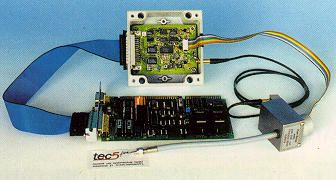
Zeiss sensor and laboratory electronics from tec5 for SIR development (Courtesy of tec5) |
Similar commercially available spectrometers in the ultraviolet and visible range could also benefit from SIR development and experience on the SMART-1 mission.
The SIR experiment is being provided by a consortium led by the Max-Planck-Institut für Aeronomie (MPAe), Garching, Germany. The principal investigator is Uwe Keller. Other members of the consortium are Carl Zeiss, Jena and tec5, Frankfurt.
MPAe has been involved in a variety of space missions. One of its cameras, for instance, was on ESA's Giotto probe and took the first pictures of the nucleus of Halley's comet. Another on the Mars Pathfinder lander provided spectacular pictures of the Martian terrain.
D-CIXS & XSM
The Demonstration of a Compact Imaging X-ray Spectrometer (
 |
|
|
Mapping the lunar surface composition
Lunar resource evaluation, for example determining sites rich in magnesium and titanium may be useful when deciding future landing sites for manned lunar exploration.
While surveying the night side of the Moon,
And on the way to the Moon...
During
Smallest X-ray spectrometer
 |
|
|
The other innovative feature of the spectrometer is its Advanced Micro-structure Collimator which ensure that only X-rays from a single well-defined direction reach the detectors. In the past, such devices would have involved large pieces of metal. The same effect is now achieved with less than a millimetre thickness. The Collimator with its associated filters also rejects solar wind particles and radiated heat from the lunar surface.
Precursor for Mercury
"All in all", says Manuel Grande, "
XSM
In order for
XSM (
In addition to being a part of the
XSM consists of two main components, a sensor unit and an electronics board. The sensor unit is mounted externally on one of the panels of the spacecraft and contains a Peltier cooled, high-purity silicon PIN radiation detector, the detector's front-end electronics and an electro-magnetically controlled shutter for protective shielding of the detector during
The XSM electronics board is situated in the
| XSM characteristics | |||
| Field of view | 52 degree cone | ||
| Effective spectral range | 1 - 20 keV | ||
| Spectral channels | 512, equally spaced | ||
| Spectral resolution (at 6 keV) | 250 eV (BoL), < 350 eV (EoL) | ||
Laser Link
In 1977, ESA placed the first technological study contract in the field of space laser communications. Today - with two independent companies developing laser communication terminals - Europe is in a leading position in the domain of optical communications.
 |
|
Laser Link Experiment |
As part of the SILEX programme, ESA has also constructed an Optical Ground Station (OGS) on the Canary Islands. The OGS was used for commissioning and routine checkout, of the Artemis satellite and can simultaneously receive and transmit data.
Whereas SILEX has demonstrated optical communication between Earth and Artemis in its fixed position at 36 000 km, the SMART-1 Laser-Link Experiment will allow the study of the effects of the laser beam passing through different air masses and with the target spacecraft at varying distances from Earth.
An optical communication link, in which a laser beam is used to convey signals, is much more direct than a radio frequency link and can thus cover greater distances. The use of very high frequencies (laser) also permits a very wide bandwidth, meaning that a greater amount of information can be transmitted in less time as compared to a radio signal. (The interest in higher frequencies is also to be seen in SMART-1's KaTE experiment).
The shower curtain effect
While the influence of the atmosphere on optical beams from space to ground can be routinely monitored by observing stars, its influence on optical beams from ground to space can only be evaluated theoretically. It is well known that the atmosphere's influence on laser beam propagation is very different for the two cases.
This difference in behaviour is also called 'shower curtain effect' and it can indeed be observed by looking through a transparent shower curtain while taking a shower. The view from the inside out (from behind the shower curtain) is very much blurred, while the view from the outside in (from some metres away from the shower curtain) is comparatively clear.
The SMART-1 laser-link experiment is ideally suited to monitor those effects of the atmosphere on a laser beam from ground to space and in different conditions (for example varying distances, heights above horizon).
The Earth's atmosphere is not benign when optical communications are concerned. Absorption by water vapour can reduce the energy content in the communication beam and turbulence can increase the beam's divergence. A laser beam generally propagates in a straight line, but atmospheric turbulence can deviate its path. The laser beam's coherence (the way its electromagnetic waves are phased with one another) can also be altered by atmospheric turbulence.
High power and pin-point accuracy
 |
|
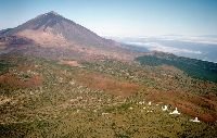
Observatorio del Teide, Tenerife (Credits: Instituto de Astrofisica de Canarias) |
The OGS transmitter uses a Ti:Sapphire laser pumped by a 28 Watt Argon laser. In order to generate 28 Watts of optical power the Argon laser consumes 60 kilowatts (!) of electrical power. This energy is partly used to heat the OGS, but most of it is dissipated by radiators outside the OGS.
The wavelength of the Ti:Sapphire can be automatically set between 750 nm and 900 nm. For the SMART-1 experiment it will be tuned to 847 nm, the same wavelength as used in the SILEX experiment. The laser's output power is some six watts. A new laser transmission technique will be used by producing four incoherent sub-aperture beams, affected differently as they pass through the atmosphere, but whose net result will be a more consistent signal received by the target.
The laser-link experiment will be performed by pointing the spacecraft's AMIE camera towards the Earth. Apart from a laser line filter which covers a section of the CCD imaging array of the camera, there is no specific laser-link equipment aboard SMART-1.
Using the spacecraft's orbital coordinates or ephemeris with respect to stellar background (as seen in the field of view of the OGS telescope), the Tenerife station will aim the laser beam at the spacecraft. The laser will be just a pure carrier and it is not intended to transmit any actual information. The pointing accuracy required is <10 microradians, equivalent to shooting at a 1.5 cm diameter coin from a distance of 1500 metres.
The laser-link demonstration is being conducted by ESA's Directorate of Technical Operations Support at ESTEC and the experiment's technology investigator is Zoran Sodnik.
KaTE & RSIS
Space communications are today part of everyday life. Direct television broadcasting, satphones and Internet via satellites in Earth orbit bring information into our homes at the speed of light. But once we leave the immediate vicinity of our planet, communicating in space, for instance with science probes, is more complex and challenging.
Such communication links have to be extremely reliable the further a spacecraft travels from Earth. Establishing contact over millions of kilometres requires adequate transmission power at ground tracking stations. Spacecraft need very sensitive receivers and correctly orientated antennae that will be able to communicate with Earth.
As missions become more ambitious, the importance of the collected science data that needs to be sent back increases. But power being limited, larger spacecraft antennae problematic and the less frequent occasions when the spacecraft and Earth are able to communicate, require that alternative methods need to be devised.
Advanced deep space communications
The SMART-1 mission will be contributing to this key area of space technology with the deep space X/Ka-band Telemetry and Telecommand Experiment (KaTE). The experiment is being managed by ESTEC (TTC and Radio Navigation Section, Electrical Department), in conjunction with Dornier Satellitensysteme GmbH, Ottobrunn, Germany. The science investigators are Luciano Iess and Giovani Palmerini of the University of Rome. The principal technology investigator at ESTEC is Paul McManamon.
The KaTE objectives are to:
- validate new digital communications technology with very sensitive receivers onboard the spacecraft
- to demonstrate for the first time on a science mission the performance of a new higher range of communication frequencies in the X-band (8 GHz) and Ka-band (32/34 GHz)
- to test new data encoding techniques (Turbo code)
- and to validate the corresponding ground-based infrastructure
KaTE will make use of the DSS-13 (NASA JPL) and Villafranca (ESA) ground stations.
KaTE will also allow experiments in the field of radio science and space navigation. A Radio Science Investigation with SMART-1, RSIS, will be conducted to study the lunar libration or 'wobble', the way in which the Moon's rotational state can vary. Tracking the spacecraft much more accurately, by means of a greater precision in measuring the Doppler shift in the X-band and Ka-band, will also give further insights into the performance of the SMART-1 solar electric propulsion.
Higher frequencies: more data, better science
The use of higher radio-frequency bands is dictated by the 'link performance' required when communicating with spacecraft at great distances. This covers such factors as the transmitter power, the efficiency of the antennae and the background noise levels in the onboard electronic equipment.
Higher telemetry rates (the speed at which greater volumes of data can be transmitted and received) are also important if ground stations are to be employed more efficiently and at lower cost. Interference that can be caused to other communications systems on Earth when using such high powers as required for deep space communication (20 kW) employing the current S-band, and compliance with international regulations are other considerations that lead to the use of the X and particularly Ka-bands.
SMART-1 will be demonstrating all these advantages, notably in view of ESA's projected BepiColombo spacecraft. A high rate telemetry link will be essential for this two-satellite mission which will be studying the planet Mercury and its magnetosphere.
Other projected missions with multiple satellites as Darwin will benefit from using the digital receiver technology demonstrated with KaTE as a single ground station could be used to communicate simultaneously with many such receivers.
Most of the KaTE experiment will take place during SMART-1's lunar observation phase. It will also be used experimentally to monitor spacecraft acceleration, and thus the solar propulsion performance, at any time during the mission.
Investigating lunar libration
One of the scientific and technological objectives of the Radio Science for SMART-1 (RSIS) experiment will be to study the feasibility and accuracy of determining the rotational state of a planet, or a satellite, from orbit. This has never been attempted. It will be achieved by performing precision tracking of the SMART-1 spacecraft and combining the resulting position data with the high-resolution imagery obtained from the AMIE camera and attitude data from the spacecraft's star sensor.
The RSIS libration experiment will resemble a high precision geometry exercise. The AMIE camera will offer a resolution of some 20 arcsecond per pixel, corresponding to less than 30 m on the lunar surface seen from an altitude of 300 km. The spacecraft's star tracker will give an indication of SMART-1's attitude to within 4 arcsecond and KaTE will provide ranging data with its new advanced X/Ka-band links and precision Doppler measurements. No startling scientific results are expected but processing all this information will show whether, and particularly with what accuracy, one can detect longitudinal and latitudinal lunar libration.
This RSIS assessment of the capabilities of these new communication technologies will be essential for all future deep space missions that carry geodesy and relativity experiments. One of the first applications of these capabilities will be ESA's mission to Mercury, BepiColombo.
| How long does a signal take on a round trip to and from a satellite or deep space probe? | ||
| Geostationary satellite | 36 000 km | 1/4 sseonds |
| SMART-1 around the Moon | 384 000 km | 2.5 seconds |
| Mercury | from just under 12 minutes to over 20 minutes | |
| Pioneer 10 | More than 12 thousand million km from Earth | 10 hours |
The SMART-1 multicolour micro-camera (AMIE)
Miniaturisation is an everyday feature of our daily lives. Whether it is in cars, dishwashers or home digital cameras, everything is increasingly more compact and incorporates automatic procedures. The economics of the approach play a part as, in space at least, smaller can mean smarter and cheaper. Optimising a small spacecraft is a requirement and the mass and size of a proposed instrument can be crucial when deciding if it qualifies for a place on a science mission.
 |
|
Early prototype of the micro imager (AMIE) |
Over recent years, the assessment of future space exploration missions, notably in the framework of ESA's Technological Research Programmes, has repeatedly demonstrated the desirability of highly compact, lightweight and rugged cameras. The AMIE experiment is SMART-1's opportunity to demonstrate such an instrument.
The Asteroid-Moon Micro-Imager Experiment, AMIE, is an imaging system derived from the current development efforts of ESA's Technological Research Programme and has been developed by the Centre Suisse d'Electronique et de Microtechnique (CSEM) in Neuchatel, Switzerland. The principal investigator is Jean-Luc Josset.
Lunar colour lightweight camera
The SMART-1 payload has to meet stringent mass constraints, so the AMIE unit is miniaturised as much as possible. It consists of two parts: the AMIE micro-imager camera unit and the dedicated AMIE electronics unit. The micro-imager is placed on one of the lateral panels of the spacecraft on the external side whereas the electronics unit is on the internal side of the same panel. The main functions of the system are:
- to take images with colour information
- to keep image data in a memory buffer
- to perform some image processing (data compression, image subtraction)
- to allow the downloading of the images by the on board computer
The AMIE micro-imager is a remarkably compact design, a package of dedicated optics, electronics and mechanical interfaces that weighs only 450 grams (all included). This feat has been achieved by using new microtechnology in terms of micro-mechanics, micro-optics and 3D-stack packaging. Ultra thin printed circuit boards are 'sandwiched' vertically and allow the highly dense integration into a single multi-chip module of everything required by the camera, from its CCD sensor to its connector, including all electronic components.
The AMIE electronics are composed of:
- a microprocessor board (CSEM's microprocessor) for the management of the instrument
- a micro Digital Processing Unit - DPU (IAS/CSEM) for the data compression
- a spacecraft interface board (CNR/IAS).
The design of the AMIE camera naturally takes into account the vibration stress encountered during launch, the low power consumption and wide operating temperature constraints during a space mission.
The original AMIE concept foresaw a panchromatic, 1024 x 1024 pixel image with a medium field of view of 5.3 degrees by 5.3 degrees. The camera will provide a high spatial resolution, some 50 m/pixel. Data from the micro-imager is read out and stored in the AMIE electronics, from which it can be downloaded as required from the spacecraft.
Initially a technology demonstration of a miniaturised micro-imager, AMIE on SMART-1 now has significant science objectives, covering the study of the Moon's morphology, topography and surface texture. The science community realised the potential of such a camera operating in a multi-spectral mode. AMIE has thus been equipped with four filters, one in the red (750 nm), two in the infrared (900 and 950 nm), and one specific to the Laserlink experiment (850 nm). It will also operate in white light.
AMIE will be opening new ground in the field of multi-spectral lunar observation. Whereas the multi-spectral camera aboard the American Clementine mission had constant illumination conditions, SMART-1's orbit will offer multi-angular imaging. AMIE's views at different angles correlated with Clementine data of the same lunar areas will allow scientists to establish photometric models, allowing the interpretation of such spectral data. These photometric studies will further our knowledge of the lunar surface, but will also be helpful for future multi-spectral observation of other planetary bodies, such as Mercury.
The micro-imager will work closely in conjunction with the SIR and D-CIXS instruments. Its infrared filter overlaps and complements the SIR spectrometer (900 nm - 2400 nm) and will notably allow studies of the different lunar rock types. Information obtained by AMIE and D-CIXS will help establish abundance maps of the elements present on the lunar surface.
The AMIE team
In addition to the AMIE technical team at CSEM, co-investigators in France are Patrick Pinet at the Terrestrial and Planetary Dynamics Laboratory, Toulouse, Yves Langevin at the Institut d'Astrophysique Spatiale, Orsay and Antonella Barucci at Observatoire Paris Meudon.
Italy is equally involved with co-investigators and hardware responsibilities. The co-investigators are Dr Priscilla Cerroni and Dr Maria Cristina De Sanctis, both from IAS-CNR, Rome, whose scientific interests lie in the fields of planetary sciences, physics of small Solar System bodies, impact cratering, and who have specific experience in the remote sensing of planetary surfaces from space missions. The Italian contribution to AMIE will include the DC/DC power converter and spacecraft interface board, and the development of ground support equipment software for scientific support and for the spacecraft's assembly, integration and verification activities, under the supervision of the Technical Manager Dr Andrea Di Lellis, IAS-CNR, Rome.
Other co-investigators include the Director of the Helsinki Observatory, Karri Muinonen, for the modelling of the Moon scattering light. The Institut de Géologie de l'Université de Neuchâtel (CH) are also co-investigators and part of the AMIE team. In addition to support by the SMART-1 team and project scientist, ESA/ESTEC is participating in the instrument development: Patrick Plancke for the overall technical developments and Detlef Koschny for thermal analysis of the instrument.
AMIE is supporting three other SMART- 1 investigations: the Laser-Link experiment (led by Zoran Sodnik, ESA), an autonomous navigation algorithm OBAN (Finn Ankersen, ESA) that uses image processing, and a measurement of lunar libration in coordination with the radio-science experiment RSIS. AMIE will also provide a visual record of the mission for educational and science communication purposes.