Electric Spacecraft Propulsion
Why Use Electric Propulsion?
Development of electrical propulsion systems has been stimulated by limitations in conventional chemical propulsion that derive from Newton's laws of dynamics. A rocket-propelled spacecraft derives its acceleration from the discharge of propellant and its equation of motion (neglecting gravitation and drag) follows directly from the conservation of the total momentum of the vehicle and the propellant stream:
 |
 |
Time varying (instantaneous) mass of the vehicle | ||
 |
Vehicle acceleration | ||
 |
Velocity of the exhaust stream | ||
 |
Rate of change of spacecraft mass due to propellant expulsion |
The product of the rate of mass expulsion and the exhaust velocity is the thrust generated by the propulsion system:
 |
 |
Thrust generated by propulsion system |
This thrust can be treated, for most purposes, as if it were an external force applied to the vehicle.
The integral of the thrust over the time for which it is applied is the impulse, or change of momentum. The ratio of thrust to the rate of expulsion of propellant measured in units of weight expelled per second is known as the specific impulse:
 |
 |
Specific impulse | ||
 |
Gravitational acceleration at sea level | ||
 |
Rate of expulsion of propellant measured in units of weight per second |
If the exhaust velocity is constant during the thrusting time, the spacecraft experiences an increment in velocity which is linearly dependent on the exhaust velocity and logarithmically dependent on the propellant mass ejected:
 |
 |
Increment in velocity | ||
 |
Velocity of the exhaust stream | ||
 |
Vehicle mass at beginning of thrust period | ||
 |
Vehicle mass at end of thrust period |
The deliverable mass fraction, the proportion of the spacecraft's initial mass that can be delivered to the vehicle's destination, is a negative exponential in the scalar ratio of the required velocity increment to the exhaust velocity:
 |
The velocity increment required for a given mission or manoeuvre is an indication of the energetic difficulty of that mission or operation. If a spacecraft is to deliver a large proportion of its initial mass to its destination, the deliverable mass fraction equation shows that the propulsion system exhaust velocity must be comparable to the required velocity increment.
Chemical spacecraft propulsion systems create thrust by thermodynamically expanding heated propellant gas through a nozzle. The energy to heat the propellant is stored in the chemical bonds of the propellant or propellant / oxidiser combination and released through decomposition in single propellant systems or chemical reaction in multi-propellant systems. Chemical propulsion systems are limited by the available reaction energies and thermal transfer considerations to exhaust gas velocities of a few thousand metres per second. However, many desirable future space missions require velocity increments that are an order of magnitude, or more, higher than this.
For missions that require a high velocity increment, an alternative method of propulsion having a higher specific impulse or exhaust gas velocity than can be achieved using chemically fuelled thermodynamic expansion is required. Electric spacecraft propulsion offers just this possibility.
Electric spacecraft propulsion systems create thrust by using electric, and possibly magnetic, processes to accelerate a propellant. More intense forms of propellant heating, as used in electrothermal propulsion systems, offer one possibility for increased exhaust velocity, but encounter limitations due to restrictions on the temperatures that can be sustained by engine components in contact with the propellant gas flow. Thermodynamic expansion can be abandoned in favour of direct application of body forces to particles in the propellant stream. This is the method used by electrostatic and electromagnetic propulsion systems.
|
Comparison of propulsion technologies | |||
|
Chemical |
Electric | ||
| Small monopropellant thruster | Fregat Main Engine |
SMART-1 Hall Effect Thruster | |
| Propellant | Hydrazine | Nitrogen tetroxide / Unsymmetrical dimethyl hydrazine | Xenon |
| Specific |
200 | 320 | 1640 |
| Thrust (N) | 1 | 1.96 x 10⁴ | 6.80 x 10⁻² |
| Thrust |
1.66 x 10⁵ | 877 | 1.80 x 10⁷ |
| Thrust |
46 | 0.24 | 5000 |
| Propellant |
52 | 5350 | 80 |
| Total |
1.1 x 10⁵ | 1.72 x 10⁷ | 1.2 x 10⁶ |
|
Fregat produces ~ 14 times the total impulse of SMART-1's engine, but uses nearly 70 times more propellant mass to do so. The hydrazine thruster produces less than a tenth as much total impulse while using 65% of the propellant mass. | |||
Geostationary communications satellites have used electric propulsion systems for station keeping since the early nineteen-eighties. Low Earth orbit satellites, such as the Iridium mobile communications cluster, have also used electric propulsion for orbit adjustments but the use of electric propulsion as a spacecraft's primary means of propulsion has been restricted to experimental vehicles such as NASA's Deep Space One, which was equipped with a xenon ion engine.
ESA's SMART-1 spacecraft is equipped with an electric propulsion system as its primary means of propulsion. It is intended as a technology demonstrator for the use of primary electric propulsion on future missions.
Electric versus Chemical Propulsion
While chemical propulsion systems store their energy in the propellants, the energy required by electric propulsion systems is generated by solar panels. The use of solar panels to supply power to an electric propulsion system is referred to as solar electric propulsion (SEP). Future missions, operating at high power levels or at great distances from the Sun will require an alternative source of power. If the safety concerns can be addressed, power could be provided by a nuclear electric power system, where heat from a reactor is used to produce electricity by direct thermoelectric or thermionic conversion using solid-state devices or by an indirect thermodynamic cycle.
Chemical propulsion is said to be "energy limited" because the chemical reactants have a fixed amount of energy per unit mass, which limits the achievable exhaust velocity or specific impulse. However, because the propellants are their own energy source, the rate at which energy can be supplied to the propellant (which is ultimately limited by reaction kinetics) is independent of the mass of propellant, so very high powers and thrust levels can be achieved.
Electric propulsion systems are not energy limited. Neglecting component lifetime considerations, an arbitrarily large amount of energy can be delivered (from a solar or nuclear power system) to a given mass of propellant so that the exhaust velocity (or specific impulse) can be much larger than that available from a chemical propulsion system. Electric propulsion systems are termed "power limited" because the rate at which energy from the external source is supplied to the propellant is limited by the mass available for the power system. This has the result of limiting the thrust of the electric propulsion system for a given spacecraft mass. Because of this, electric propulsion vehicles tend to be low thrust to mass ratio (and therefore low acceleration) vehicles.
Although electric propulsion vehicles have low thrust to mass ratios, they can have a larger total amount of impulse (the product of specific impulse and propellant mass, equal to the total change of momentum) than a chemical propulsion system. So, even though a chemical propulsion system can offer a high thrust to mass ratio, the propellant is expended in a short time at low specific impulse. By contrast, the low thrust to mass ratio electric propulsion system can be operated for periods ranging from hours to years and build up a larger total impulse.
Power for Electric Propulsion
Although electrical propulsion systems offer the advantage over chemical systems of much higher exhaust velocity or specific impulse, there is a penalty to be paid for this performance. The total mass of a chemical propulsion system is made up of the mass of the propellant or propellants and their storage tanks, the engine itself and the control system. Electric propulsion systems have, in addition to these components, a power source and a power controller. The mass of these components partially offsets the mass saving made by being able to fulfil the mission velocity change requirements using a reduced propellant mass.
The mass of the power supply scales in proportion to the required power:
 |
 |
Power supply mass | ||
 |
Power supply specific mass (mass per unit power) | ||
 |
Power required for propulsion |
The power required to obtain a desired thrust is given by:
 |
 |
Power required for desired thrust | ||
 |
Exhaust gas velocity | ||
 |
Thrust |
The efficiency with which the thruster converts input power into thrust power is:
 |
 |
Conversion efficiency |
It follows that the power supply mass is given by:
 |
showing that the power supply mass scales with the square of the exhaust velocity.
The required propellant mass scales inversely with the exhaust velocity so there exists, for any given required velocity change, some optimum exhaust velocity that minimises the sum of the propellant and power supply masses.
The equation for power supply mass shows the importance of achieving low power supply specific mass and high thruster conversion efficiency to reap the maximum benefit from the use of electric propulsion.
Methods of Electric Propulsion
There are three basic types of electric propulsion systems, categorised according to the method used to accelerate the propellant as electrothermal, electrostatic, and electromagnetic. Practical propulsion systems frequently make simultaneous use of two or even all three of these methods.
Electrothermal Propulsion
Electrothermal propulsion systems accelerate the propellant using heating. There are three
Resistojets
Resistojets operate by passing gaseous propellant through an electric heater and then expanding it through a conventional nozzle to create thrust. Resistojets are normally operated as enhanced chemical propulsion systems where electric heating is used to further expand and accelerate propellant that has already undergone a chemical reaction.
The most successful application of this technique to date has been the superheating of catalytically decomposed hydrazine, which offers the advantage of fuel commonality with a frequently used monopropellant chemical propulsion system.
The specific impulse that can be achieved with hydrazine resistojets is limited because the molecular mass of the gases used is relatively high and because the maximum heating surface temperature that can be sustained with available materials is limited to around 3000 K. This results in an achievable exhaust velocity of about 3500 m s-1 (Isp = 350 s) some 40% better than without superheating, with an efficiency of up to 80%.
Resistojets were first used experimentally in space during the mid nineteen-sixties. Their first operational use was for north-south station keeping on the
Arcjets
For electrothermal propulsion systems to achieve exhaust velocities much higher than 10 000 m s-1, portions of the propellant flow must attain temperatures in excess of 10 000 K while being kept out of contact with the engine component walls. Arcjets accomplish this by passing the propellant through an electric arc that heats it before it expands through a nozzle.
Core arc temperatures of 10 000 to 20 000 K mean that exhaust velocities of 5000 - 6000 m s-1 (Isp = 500 - 600 s) at efficiencies of around 40% are possible using catalytically decomposed hydrazine.
Arcjet thrusters entered commercial use for north-south station keeping on the
Inductively or Radiatively Heated Systems
Inductively or radiatively heated systems heat the propellant stream with some form of electrodeless discharge. The free electron component of the propellant gas is heated by the application of an oscillating electromagnetic field. Frequencies from low radio frequency up to microwave have been tested on the ground. No examples of this technology have yet been flown.
Electromagnetic Propulsion
Electromagnetic propulsion uses orthogonal electric and magnetic fields to apply a Lorentz body force to ionised propellant atoms, accelerating them out of the plane of the crossed fields. The electromagnetic propulsion techniques currently in use or being investigated include pulsed plasma thrusters and magnetoplasmadynamic thrusters.
Pulsed Plasma Thruster
The pulsed plasma thruster (PPT) with solid propellant is used for low power propulsion systems; typically with an average power less than thirty watts. Capacitor stored electrical energy is used to create a pulsed arc discharge across the face of a block of propellant, teflon in most implementations to date. The combination of thermal flux, particle bombardment and surface reactions ablates and ionises a small amount of the solid material (~ 1.5 µg J-1). The peak discharge current is high, in the region of tens of kA. The self-induced magnetic field acts on the ions moving in the electric field creating the discharge to create a Lorentz body force that accelerates the plasma.
Teflon PPTs have enjoyed limited use in east-west station keeping and sun pointing applications. PPTs do not produce sufficient thrust to be considered as candidates to provide primary propulsion of future out of earth orbit missions and were not considered for
Magnetoplasmadynamic Thruster
Magnetoplasmadynamic (MPD) thrusters pass a large current radially outwards through a neutral plasma, from a central cathode to an annular anode. The radial current induces an azimuthal, circular magnetic field. The Lorentz body force acting on ions moving in the discharge current accelerates the plasma along the axis of the electrode structure. MPD thrusters operate at high power levels, kilowatts to megawatts, and provide high thrust with moderate specific impulse. A variant of this design uses an externally applied magnetic field to enable operation at lower power levels.
MPD thrusters have been tested in the laboratory and have flown on test and demonstration missions. MPD thrusters are an insufficiently mature technology and consume too much power to be considered as candidates to provide primary propulsion of future out of earth orbit missions and were not considered for
Electrostatic Propulsion
Electrostatic propulsion systems accelerate the ionised propellant by means of an electric field. The principal techniques are field effect electrostatic propulsion (FEEP), colloidal thrusters, and gridded ion accelerators.
Field Effect Electrostatic Propulsion
Field Effect Electrostatic Propulsion (FEEP) is based on the ability of a strong electric field
Colloidal Thruster
Colloidal thrusters work by electrostatically accelerating charged,
Colloidal thrusters are an insufficiently mature technology to be considered as candidates to provide primary propulsion for future out of earth orbit missions and were not considered for
Ion Engine
In gridded electrostatic ion accelerators, also known as ion engines, ions are produced in a magnetically contained ionisation chamber by a direct current discharge, radio frequency energy or tuned electron cyclotron resonance. The exit from the ionisation chamber is covered by a double-grid structure with a space between the grids of around half to one millimetre, across which the ion acceleration potential is applied. Ions that move near to the inner (screen) grid are extracted from the chamber and accelerated by the field between the grids. The ion optics are arranged so as to minimise collisions with the outer, accelerating grid. Electrons are extracted from the chamber by an anode and pumped by the power supply to an external cathode/neutraliser held slightly above the potential of the accelerating grid. The electrons from the cathode combine with the exiting ion stream to neutralise it. Neutralisation of the ion stream is necessary because ejecting charged particles from a spacecraft causes the vehicle itself to acquire a charge, which affects the operation of other spacecraft systems and may cause permanent damage. Also, without neutralisation the emerging ion beam would stall on its own internal potential profile.
Ion thrusters achieve exhaust velocities in the region of 30 000 m s-1 (Isp = 3000 s). ESA's EURECA spacecraft demonstrated the operation of RITA, an ion thruster employing radio frequency ionisation, in 1992. Ion thrusters have been in operational use since the mid nineteen-nineties for station keeping on geostationary satellites. In 1998, NASA's Deep Space 1 became the first interplanetary mission to use ion propulsion.
Ion thrusters suffer from low thrust density (available thrust per unit exhaust area) because the maximum ion current density that can be sustained is limited by space-charge distortions of the applied electric field. One advantage of the Hall effect thruster selected for
Hall Effect Thrusters
Hall effect thrusters have been classed as both electrostatic and electromagnetic propulsion systems. An electrostatic field accelerates the ions in the propellant stream but that field is, to a large extent, produced by the actions of plasma electrons interacting with a magnetic field, giving both classes a claim to the technique.
In Hall effect thrusters, also referred to as closed drift thrusters, a heavy gas, xenon in most implementations to date, is ionised and accelerated by an electric field. An electron current passing through and being impeded by a magnetic field establishes the acceleration field. The precessing electrons in this magnetic field follow a closed drift path, giving rise to one of the names for this technique. The flow of the drifting electrons, which is perpendicular to both the applied magnetic field and the current flow in the plasma, is due to the Hall effect, the source of the other name for this type of thruster.
The mechanical configuration of a Hall effect thruster is an annular discharge chamber in which a radial magnetic field is established between an inner, cylindrical ferromagnetic pole piece and an outer, ferromagnetic ring. The chamber is closed at one end, where an annular anode is situated. The other end of the chamber is open and forms the exit path for the accelerated ions. Outside the chamber, beyond the exit for the ion stream, is an external cathode. As the electrons emitted by the cathode move towards the anode under the influence of the applied electric field, the radial magnetic field results in a force acting on them in a direction perpendicular to the plane containing the two fields, which causes them to drift in an azimuthal direction. This azimuthal drift results in a Hall current and impedes the progress of the electrons towards the anode.
The Hall current is the result of the electrons gyrating around the magnetic field lines in a plane parallel to the applied electric field. The gyroradius is larger when the electron is being accelerated by the electric field (moving towards the anode) than when it is being decelerated by it (moving towards the cathode), giving rise to a net azimuthal drift, the classical Hall effect. An appropriate choice of magnetic field strength (typically a few tens of mT) and axial field profile results in the electrons being effectively trapped in a closed-drift azimuthal orbit near the area of maximum field strength, where collisions between electrons and with ions, neutral particles and the chamber walls permit a slow diffusion of electrons towards the anode.
Due to the lack of axial electron mobility, the plasma can sustain a very high electric field along the axis of the discharge chamber. The trapped electrons form a 'virtual cathode' held at very nearly the same potential as the external real cathode. Propellant atoms are introduced through holes in the annular anode. These atoms are ionised by collisions with the azimuthally drifting electrons soon after entering the discharge. The propellant ions are then accelerated by the axial electric field, generating thrust that is transmitted to the structure of the thruster by the interaction between the Hall current and the magnets creating the radial field. As the accelerated propellant ions exit the discharge chamber, additional electrons from the external cathode are used to neutralise them.
The neutralisation of the exiting ion stream is necessary to prevent the spacecraft from acquiring a charge, which might result in equipment malfunction or even damage, if the charge were allowed to build to the point where discharges occurred.
The proper operation of a Hall thruster is dependant on the strength and axial profile of the magnetic and the relation of these parameters to the geometry of the discharge chamber. The magnetic field strength must be such that the electrons are trapped in the chamber, unable to move directly to the anode and cause a short circuit, while propellant ions are able to escape. This is achieved by arranging for the length of the discharge region to be greater than the gyroradius of the electrons but much less than the gyroradius of the ions. In order to achieve stable ion flow, the strength of the radial magnetic field should increase with increasing axial distance from the anode. The magnetic field maximum defines the end of the ion acceleration zone and needs to be located within the acceleration chamber.
Hall / closed drift thrusters are divided into two types, stationary plasma thruster (SPT) and thruster with anode layer (TAL), based both on geometrical and material differences in the discharge channels of the two types, and on the different physical processes that take place within the discharge plasma.
In the stationary plasma thruster, the acceleration channel length is comparable to or greater than the diameter of the discharge chamber and the walls of the chamber are composed of a dielectric, ceramic material (usually boron nitride) that serves to protect the magnet poles from plasma erosion. The thruster with anode layer has a very short acceleration channel and the discharge plasma is positioned downstream of the thruster exit plane, obviating the need for protecting the magnet poles.
Although the two types of thruster are similar in layout and operating principle, the different materials and mechanical configurations used for the acceleration channels greatly change the underlying physics of operation of the thruster variants.
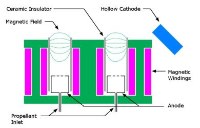 |
|
Schematic cross section of stationary plasma thruster |
The dielectric material used for the walls of the SPT has an emission coefficient for secondary electrons emitted following impact by gyrating electrons of approximately one. The high electron re-supply rate due to secondary emission limits the potential drop across the plasma sheath adjacent to the chamber wall and a large number of discharge electrons are able to reach the chamber wall. The effect of the presence of the dielectric material is to limit the kinetic energy of the confined electrons. As trapped electrons diffuse toward the anode their kinetic energy is increased by the applied electric field. When one of these higher-energy electrons impacts the dielectric wall it is absorbed and a much less energetic secondary electron is emitted. The result of the collision/secondary emission process is that the dielectric wall serves to substitute hot electrons with colder electrons. By limiting the discharge electron energy, a smooth and continuous variation in plasma potential between the anode and the cathode results. This is the type of thruster selected for
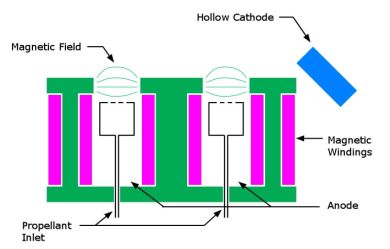 |
|
Schematic cross section of thruster with anode layer |
In contrast, the thruster with anode layer has discharge chamber walls made of a conducting metal with a much lower secondary electron yield. Additionally, these walls are maintained at cathode potential, thereby greatly reducing the incidence of gyrating electron impact with the walls. As the electrons diffuse towards the anode their kinetic energy increases significantly. Near the anode the electrons become sufficiently energetic that the upstream thermal diffusion towards the cathode becomes equal to the applied electric field diffusion towards the anode. At this point a very abrupt, discontinuous potential jump occurs in the plasma over a very thin layer near the anode, hence the term thruster with anode layer.
SMART-1 Propulsion System
The thruster selected for primary propulsion on
 |
|
Artist's impression of SMART-1's ion engine in operation. |
In addition to the thruster, the electric propulsion system is composed of the following components:
- Power processing unit, which controls the electrical functions of the thruster
- Pressure regulator, which supplies gas from the storage tank to the flow control unit at the required pressure
- Remote terminal unit, which interfaces the propulsion system components to the spacecraft command and telemetry systems
- Electrical filter unit, which suppresses the conducted electromagnetic emissions produced by the discharge current
- Xenon flow control unit, which modulates the mass flow rate of gas entering the thruster
- Propellant storage tank with a volume of 49 litres, capable of storing 82 kilograms of xenon at a pressure of 150 bar
- Thruster orientation mechanism, to allow adjustment of the direction of thrust relative to the spacecraft axes
- Harness and piping connecting the various components together