Engineering
Introduction
The Huygens Probe will be delivered to Titan, Saturn's largest satellite, by the Cassini Orbiter in 2004. After an interplanetary journey of 6.7 years - during which Huygens will be dormant except for health checks every six months - its aeroshell will decelerate it in less than three minutes from an entry speed of 6 km s-1 to 400 m s-1 (Mach 1.5) at about 160 km altitude. From then on, a pre-programmed sequence will trigger parachute deployment and heatshield ejection. The main scientific mission can then begin, lasting for the whole 2 - 2.5 hour descent.
Built by an industrial consortium led by Aerospatiale, the Probe System comprises two principal elements:
- the 318 kg Huygens Probe, which enters Titan's atmosphere after separating from the Saturn Orbiter
- the 30 kg Probe Support Equipment (PSE), which remains attached to the Orbiter after Probe separation
The Probe itself consists of the Entry Assembly (ENA) cocooning the Descent Module (DM). The ENA provides Orbiter attachment, umbilical separation and ejection, cruise and entry thermal protection, and entry deceleration control. It is jettisoned after entry, releasing the Descent Module.
The DM comprises an aluminium shell and inner structure containing all the experiments and Probe support subsystems, including the parachute descent and spin control devices.
The PSE consists of:
- four electronic boxes aboard the Orbiter: two Probe Support Avionics (PSA), a Receiver Front End (RFE) and a Receiver Ultra Stable Oscillator (RUSO)
- the Spin Eject Device (SED)
- the harness (including the umbilical connector) providing power and RF and data links between the PSA, Probe and Orbiter.
Mechanical & Thermal Subsystems
Front Shield Subsystem (FRSS)
The 79 kg, 2.7 m diameter, 60° half-angle coni-spherical Front Shield will decelerate the Probe in Titan's upper atmosphere from about
The FRSS supporting structure is a CFRP honeycomb shell, to the AQ60 tiles are attached by adhesive CAF/730. Prosial, a suspension of hollow silica spheres in silicon elastomer, is sprayed directly on to the aluminium structure of the FRSS rear surfaces, where fluxes are ten times lower.
Back Cover Subsystem (BCSS)
The Back Cover protects the DM during entry, ensures depressurisation during launch and carries multi-layer insulation (MLI) for the cruise and coast phases. Since it does not have to meet stringent aerothermodynamic requirements, it is a stiffened aluminium shell of minimal mass (11.4 kg) protected by Prosial (5 kg). It includes: an access door for late access during integration and for forced-air ground cooling of the Probe; a break-out patch through which the first (drogue) parachute is fired; a labyrinth sealing joint with the Front Shield, providing a non-structural thermal and particulate barrier.
Descent Control Subsystem (DCSS)
The DCSS controls the descent rate to satisfy the scientific payload's requirements, and the attitude to meet the requirements of the Probe-Orbiter RF data link and of the descent camera's image-taking.
The DCSS is activated nominally at Mach 1.5 and about 160 km altitude. The sequence begins by firing the Parachute Deployment Device (PDD) to eject the pilot chute pack through the Back Cover's break-out patch, the attachment pins of which shear under the impact. The 2.59 m diameter Disk Gap Band (DGB) pilot chute inflates 27 m behind the DM and pulls the Back Cover away from the rest of the assembly. As it goes, the Back Cover pulls the 8.30 m diameter DGB main parachute from its container. This canopy inflates during the supersonic phase to decelerate and stabilise the Probe through the transonic region. The Front Shield is released at about Mach 0.6. In fact, the main parachute is sized by the requirement to provide sufficient deceleration to guarantee a positive separation of the Front Shield from the Descent Module.
The main parachute is too large for a nominal descent time shorter than 2.5 hours, a constraint imposed by battery limitations, so it is jettisoned and a 3.03 m diameter DGB stabilising parachute is deployed. All parachutes are made of Kevlar lines and nylon fabric. The main and stabiliser chutes are housed in a single canister on the top platform of the DM. A swivel using redundant low-friction bearings in the connecting riser of both the main and stabiliser chutes ensures the lines do not tangle as the Probe spins.
Separation Subsystem (SEPS)
SEPS provides: mechanical and electrical attachment to, and separation from, the Orbiter; the transition between the entry configuration ('cocoon') and the descent configuration (DM under parachute). The three SEPS mechanisms are connected on one side to Huygens' Inner Structure (ISTS) and on the other to the Orbiter's supporting struts. As well as being the Probe-Orbiter structural load path, each SEPS fitting incorporates a pyronut for Probe-Orbiter separation, a rod cutter for Front Shield release and a rod cutter for Back Cover release.
Within SEPS, the Spin Eject Device (SED) performs the mechanical separation from the Orbiter:
- three stainless steel springs provide the separation force
- three guide devices, each with two axial rollers running along a T-profile helical track, ensure controlled ejection and spin, even in degraded cases such as high friction or a weak spring
- a carbon fibre ring accommodates the asymmetrical loads from the Orbiter truss and provides the necessary stiffness before and after separation
- three pyronuts provide the mechanical link before separation
In addition, the Umbilical Separation Mechanism of three 19-pin connectors, which provide Orbiter-Probe electrical links, is disconnected by the SED
Inner Structure Subsystem (ISTS)
The ISTS provides mounting support for the Probe's payload and subsystems. It is fully sealed except for a vent hole of about
- the 73 mm thick aluminium honeycomb sandwich Experiment Platform; supports the majority of the experiments and subsystems units, together with their associated harness
- the 25 mm thick aluminium honeycomb sandwich Top Platform; supports the Descent Control Subsystem and Probe RF antennas, and forms the DM's top external surface
- the After Cone and Fore Dome aluminium shells, linked by a central ring three radial titanium struts; interface with SEPS and ensure thermal decoupling, while three vertical titanium struts link the two platforms and transfer the main parachute deployment loads
- 36 spin vanes on the Fore Dome's periphery; provide a controlled spin rate during descent
- the secondary structure; for mounting experiments and equipment
Thermal Subsystem (THSS)
While the PSE is thermally controlled by the Orbiter, the Probe's THSS must maintain all experiments and subsystem units within their allowed temperature ranges during all mission phases. In space, the THSS partially insulates the Probe from the Orbiter and ensures only small variations in the Probe's internal temperatures, despite the incident solar flux varying from
Probe thermal control is achieved by:
- MLI covering all external surfaces, except for the small 'thermal window' (see below) of the Front Shield
- 35 Radioisotope Heater Units (RHUs) on the Experiment and Top Platforms continuously providing about one Watt each even when the Probe is dormant
- a white-painted
0.17 m2 thin aluminium sheet on the Front Shield's forward face acting as a controlled heat leak (about eight Watts during cruise) to reduce the sensitivity of thermal performances to MLI efficiency
The MLI is burned and torn away during entry, leaving temperature control to the AQ60 high-temperature tiles on the Front Shield's front face, and to Prosial on the Front Shield's aft surface and on the Back Cover.
During the descent phase, thermal control is provided by foam insulation and gas-tight seals. Lightweight open-cell Basotect foam covers the internal walls of the DM's shells and Top Platform. This prevents convection cooling by Titan's cold atmosphere (70 K at 45 km altitude) and therefore thermally decouples the units mounted on the Experiment Platform from the cold aluminium shells. Gas-tight seals around all elements protruding through the DM's shell minimise gas influx. In fact, the DM is gas tight except for a single
Heat Shield
|
|
|
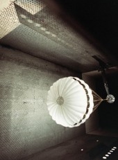
Cutaway of the Huygens probe. |
While acting as a powerful brake to slow the Probe, the Front Shield will bear the brunt of the thermal and mechanical stresses. The silica-fibre tiles that cover it must prevent the temperature in the carbon-fibre honeycomb behind them rising above 1800 K. The engineers are not certain what extra thermal load will be generated if the Probe's journey through Titan's atmosphere causes chemical reactions to occur. They have therefore left a wide safety margin in their tile design.
|
|
|
The Journey Through the Atmosphere |
Removal of the Probe from its entry protection will occur in two quick steps. The pilot parachute will pull off the previously separated Back Cover, and release the main parachute. While the main parachute slows the Descent Module, the Front Shield will fall away. A quarter of an hour later the smaller stabilizer parachute will replace the main parachute.
The descent to the surface of Titan will take 120 to 150 minutes in all, in the phases shown in the accompanying diagram.
Testing the Heat Shield
The Huygens venture literally hangs on the three different parachutes that must control the Probe's speed and attitude at successive phases of the descent on to Titan. A pilot parachute about 2.5 m in diameter, adapted to supersonic speeds, will check the headlong rush into the atmosphere and release the main parachute, about eight meters in diameter. This will operate for about 15 minutes in the thin upper layers of Titan's stratosphere. It will then be replaced by the stabilizer parachute, which is about three meters in diameter. This size of parachute for the main phase of the descent is selected to ensure that the Probe will reach the surface before the batteries go flat.
In the drop test in Sweden the Huygens model reached Mach 0.8 before the pilot chute was deployed. This could not match the full Mach 1.5 velocity at which it will operate on Titan. Wind-tunnel tests have validated the performance of the pilot chute at supersonic speed.
|
|
|
|
Test of pilot parachute in a supersonic wind tunnel. Image: Martin-Baker Aircraft Company. |
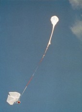
Launch of test model and balloon. |
Much engineering effort has gone into developing the parachutes and the system that deploys and jettisons them. This starts with an explosive piston that ejects the pilot chute. The same system is responsible for extracting the descent module from its protective coverings. The Earth's air substituted for Titan's atmosphere in a high-altitude drop test that verified the complex sequence.
In May 1995 a 100 m helium balloon lifted a full-scale model of Huygens 37.5 km above the Esrange upper-atmosphere facility at Kiruna, Sweden. The model Probe was released from the gondola hanging underneath the balloon. After gathering speed, it went into the whole automatic procedure to release the parachutes and shed the back cover and front shield. Instruments and cameras in the model Probe recorded the performances of the separation mechanisms and of the parachutes.
The stabilizer chute on which Huygens will make its landing on the surface of Titan was known to be insufficient to slow the test Probe for a soft impact on the Earth. A fourth and larger parachute was therefore added for the test, to achieve the intended impact speed of
"The drop test was very exciting," says Hamid Hassan of ESA. "It was almost like a project within a project, but the effort was well rewarded. The complete success of the test gives us confidence that what Huygens did at Kiruna it can do again more than a billion kilometres away, on Titan."
 |
|
Huygens descent module after landing at Kiruna. |
Electrical Power Subsystem
The EPSS consists of:
- Five batteries, which provide power from the time of Orbiter separation until at least 30 minutes after arrival on Titan's surface. Each battery comprises two modules of 13 LiSO2 (7.6 Ah) cells in series
- A Power Conditioning & Distribution Unit (PCDU), which provides the power conditioning and distribution to the Probe's equipment and experiments via a regulated main bus, with protection to ensure uninterrupted operations even in the event of single failure inside or outside the PCDU
During the cruise phase, the Probe is powered by the Orbiter and the PCDU isolates the batteries. The five interface circuits connected to the Orbiter's Solid State Power Switches (SSPSs) provide Probe-Orbiter insulation and voltage adaptation between the SSPS output and the input of the PCDUs Battery Discharge Regulator (BDR) circuits. The BDRs condition the power from either the Orbiter or the batteries and generate the 28 V bus, controlled by a centralised Main Error Amplifier (MEA). The distribution is performed by active current limiters, with the current limitation adapted for each user and with on/off switching capability.
The Mission Timer, however, is supplied by three switchable battery voltage lines through series fuses or, when the PCDU is powered by the Orbiter, by dedicated output voltage lines of the Orbiter interface circuits.
The PCDU also provides a protected +5 V supply used by the Pyro unit to generate the bi-level status telemetry of the selection relays and for the activation circuit that switches on the Pyro unit's energy intercept relay.
A Pyro Unit (PYRO) provides two redundant sets of 13 pyro lines, directly connected to the centre taps of two batteries (through protection devices), for activating pyro devices. Safety requirements are met by three independent levels of control relays in series in the Pyro Unit. as well as active switches and current limiters controlling the firing current. The three series relay levels are: energy intercept relay (activated by PCDU at the end of the coast phase); arming relays (activated by the arming timer hardware); selection relays (activated by Command and Data Management Unit, CDMU. software). In addition, safe/arm plugs are provided on the unit itself for ground operations.
|
Electrical Power Subsystem - Operational Modes | ||
|
Mission Phase |
Operations Description | |
|
Cruise |
The EPSS is completely off throughout the cruise phase, except for periodic checkout operations. There is no power at the Orbiter interface and direct monitoring by the Orbiter allows verification that all the relays are open and that the PCDU temperature (representative of all units within the inert Probe) is within limits. | |
|
Cruise Checkout |
The EPSS is powered by the Orbiter for cruise checkout operations. The 28 V bus is regulated by the EPSS BDRs associated with each Orbiter SSPS; a total of 210 Watts is available from the Orbiter. All the relays remain open during the check-out. | |
|
Timer Loading |
Following the loading (from the Orbiter) of the correct coast time duration into the Mission Timer Unit, battery depassivation is performed to minimise any energy loss due to ageing of the chemically active surfaces within the battery during cruise. Before Probe separation, the EPSS timer relays are closed to supply the Mission Timer from the batteries and the Orbiter power is switched off. | |
|
Coast to Titan |
Only the Mission Timer is supplied by batteries through specific timer relays during the coast phase. The EPSS is off and all other relays are open. | |
|
End of Coast - Probe |
At the end of the coast phase, the Mission Timer wakes the Probe by activating the EPSS. Input relays are closed and the current limiters powering the CDMU are automatically switched on as soon as the 28 V bus reaches its nominal value (other current limiters are initially off at power up). The pyro energy intercept relay is also automatically switched on by a command from the PCDU. | |
|
Entry and Descent |
All PCDU relays are closed and the total power (nominal 300 W, maximum 400 W) is available on the 28 V distribution outputs to subsystems and equipment. The Pyro Unit performs the selection and the firing of the pyros, activated by CDMU commands. | |
Probe Data Relay Subsystem
The PDRS is Huygens' telecommunications subsystem, combining the functions of RF link, data handling and communications with the Orbiter. It transmits science and housekeeping data from the Probe to the Orbiter-mounted PSE, which are then relayed to the Orbiter CDS via a Bus Interface Unit (BIU). In addition, the PDRS is responsible for TC distribution from the Orbiter to the Probe by umbilical during the ground and cruise checkouts. The PDRS comprises:
- two hot-redundant S-band transmitters and two circularly polarised Probe Transmitting Antennas (PTAs) on the Probe
- a Receiver Front End (RFE) unit (enclosing two Low Noise Amplifiers and a diplexer) and two Probe Support Avionics (PSA) units on the Orbiter
The Orbiter's High Gain Antenna (HGA) acts as the PDRS receive antenna.
In addition, as part of the Doppler Wind Experiment (DWE), two ultra stable oscillators are available as reference signal sources to allow the accurate measurement of the Doppler shift in the Probe-Orbiter RF link: the Transmitter Ultra Stable Oscillator (TUSO) on the Probe and the Receiver Ultra Stable Oscillator (RUSO) on the Orbiter.
The PDRS electrical architecture is fully channelised for redundancy, except that TUSO and RUSO are connected to only one chain.
Command & Data Management Subsystem
The Command and Data Management Subsystem (CDMS) has two primary functions:
- autonomous control of Probe operations after separation
- management of data transfer from the equipment, subsystems and experiments to the Probe transmitter for relay to the Orbiter
The data are stored redundantly on the Orbiter's two Solid State Recorders (SSRs) for subsequent downlink to Earth when the Orbiter has been reoriented to its normal attitude with its HGA Earth-pointing. (During cruise checkouts, this attitude allows direct data downlink if NASA Deep Space Network (DSN) coverage is available).
The driving requirement of the CDMS design is intrinsic single point failure-tolerance. As a result of the unusual Huygens mission (limited duration and no access by telecommand after separation), a very safe redundancy scheme has been selected. The CDMS therefore comprises:
- two identical CDMUs
- a triply redundant Mission Timer Unit (MTU)
- two mechanical g-switches (backing up MTU)
- triply redundant Central Acceleration Sensor Unit (CASU)
- two sets of two mechanical g-switches (backing up CASU)
- a Radial Acceleration Sensor Unit (RASU) with two accelerometers
- two Radar Altimeter proximity sensors, each comprising separate electronics, transmit antenna and receive antenna
The two CDMUs each execute their own POSW simultaneously and are configured with hot redundancy (Chain A and Chain B). Each hardware chain can run the mission independently. They are identical in almost all respects with the following minor differences facilitating simultaneous operations and capitalising on the redundancy:
- telemetry is transmitted at two different RF frequencies
- Chain B telemetry is delayed by about six seconds to avoid loss of data should a temporary loss of the telemetry link occur (e.g. due to an antenna misalignment if the Probe oscillates excessively beneath the parachute)
Each CDMU chain incorporates a health check (called the Processor Valid status) which is reported to the experiments in the Descent Data Broadcasts (DDBs). Either chain will declare itself invalid when two bit errors in the same memory word, an ADA exception or an under-voltage on the five V line occur within the CDMU.
Software
The Huygens software consists of that running in the Probe CDMS, referred to as Probe Onboard Software (POSW), and that within the PSA on the Orbiter, referred to as the Support Avionics Software (SASW). The POSW output telemetry is relayed via the SASW and then Cassini's CDS to the ground. The redundant data handling hardware (CDMUs and PSAs) run identical copies of POSW and SASW.
The software is based on a top-down hierarchical and modular approach using the Hierarchical Object-Oriented Design (HOOD) method and, except for some specific low level modules, is coded in ADA. The software consists, as much as possible, of a collation for synchronous processes timed by a hardware reference clock (eight Hz repetition rate). In order to avoid unpredictable behaviour, interrupt-driven activities are minimised. Such a design also provides for better software observability and reliability.
The processes are designed to use data tables as much as possible. Mission profile reconfiguration and experiment polling can therefore be changed only by reprogramming these tables. This is possible via an EEPROM. In order to avoid a RAM modification while the software is running (which can lead to unpredictable behaviour and unnecessary complexity), direct RAM patching is forbidden.
The POSW communicates with the SASW in different ways depending on mission phase. Before Probe separation, the two software subsystems communicate via an umbilical that provides both command and telemetry interfaces. Huygens cannot be commanded after separation, and telemetry is transmitted to the Orbiter via the PDRS RF link.
The overall operational philosophy is that the software runs the nominal mission from power-up without checking its hardware environment or the Probe's connection or disconnection. The specific software actions or inhibitions required for ground or flight checkout must therefore be invoked by special procedures, activated by the delivery of specific telecommands to the software.
To achieve this autonomy, POSWs