Successful Planck RF Telescope Test at 320 GHz
24 October 2007
This article reports on the recently concluded Planck Radio Frequency Qualification Model (RFQM) test campaign in the Thales Alenia Space Compact Antenna Test Range (CATR) facility, Cannes, France. The campaign gave to engineers and scientists confirmation that the planned RF verification method of the alignment of the Flight Model (FM) telescope is completely operational and can be performed with confidence on the FM spacecraft early next year.The success of this test campaign is due to exceptional team work from industry (Thales Alenia Space), ESA and the Planck Science community. It should be noted that the ESA Planck project has been strongly supported by personnel from the technical directorate at ESTEC, both in the definition and execution of the campaign and antenna RF predictions. This overall excellent collaboration has allowed an innovative testing method to be successfully implemented.
Testing Method
 |
|
Figure 1. Planck Focal Plane Unit with reference test horn indicated by the arrow |
The entire test was designed for and executed under ambient temperature and pressure conditions. This is in contrast to the eventual flight conditions for the telescope of an operational cryogenic temperature of 40 K under vacuum. As the flight detectors in the focal plane of the telescope do not operate at ambient, a special test horn was designed and implemented for the test. The test method was based on "Radar Cross Section" (RCS) measurements with a dedicated switching diode in place of a detector at the end of the feed horn waveguide. The diode is "modulated", with a bias voltage between two states corresponding to reflective and absorbing for the 320 GHz illuminating signal. The purpose of the test is to derive, from the difference between these two reflective states, the antenna pattern.
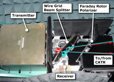
To accomplish this, a quasi-optical illuminator (QOI) was designed and implemented for the test - see figure 2. It is placed at the feed position of the CATR. The QOI can be described in RF terms as a circulator utilizing quasi-optical techniques allowing two-way reflectivity measurements.
 |
|
Figure 2. The quasi-optical illuminator |
An additional essential configuration of the CATR was the implementation of frequency sweep operation of the quasi-optical illuminator modules. The transmitter and receiver were swept through a 1 GHz bandwidth, allowing a range depth resolution of a few cm to be achieved.
Measurements and Results
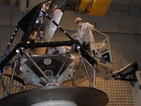
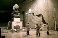
Nine individual measurements were made of the RCS response of the telescope. Each measurement corresponded to a different focus position of the test horn that was moved incrementally along the optical axis direction in 1 mm steps. For each measurement the shim combination had to be manually changed. This was a very difficult and precise operation, carried out under challenging conditions (five to six metres above ground) with limited access to the focal plane of the telescope.
 |
|
 | |
|
Figures 3, 4 & 5. The Planck RFQM in the CATR during shimming operation with diving board | |
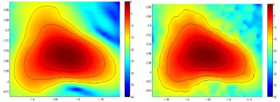
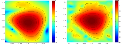
The measurement results achieved match extremely well with predictions (see figures 6 and 7). This confirms that the technique can and will be applied as a final alignment check on the Planck telescope on the FM spacecraft early next year.
 |
|
Figure 6. Prediction (left) and measurements (right) of the out of focus beam pattern with an 8mm shim behind the test feed horn |
 |
|
Figure 7. Prediction (left) and measurements (right) of the out of focus beam pattern with a 2mm shim behind the test feed horn |
