Far Infrared Interferometer
Science Objectives
Formation and evolution of stars
Stars are born in cores of collapsing dense molecular clouds of gas, obscured by surrounding dust which prevents them from being studied directly at visible wavelengths. FIRI would be able to penetrate the clouds in the far infrared to investigate the collapse of the protostar and obtain spectral maps allowing the internal chemical structure to be analysed. FIRI would also be able to shed light on the formation of binary stars, the process of which is not yet well understood.
Formation and evolution of planetary systems
FIRI would be able to image the circumstellar disks around protostars. This would allow protoplanets to be indirectly detected by the resonances they produce in the circumstellar disk.
Formation and evolution of galaxies
FIRI could contribute to the study of the Cosmic Infrared Background (CIB) by resolving the radiation into discrete contributions from the different sources. This would allow the study of the red shifted starlight of distant sources as well as reradiated emission from dust to determine the star formation rates and metal production as a function of time in the cosmic history. In addition, warm dust continuum emission from HII regions and supernovae remnants could be studied.
To fulfil these objectives, the FIRI would need to adhere to the following requirements:
| FIRI science requirements | |
| Waveband | 25-300 μm |
| Angular Resolution | < ~1.5" at 200 μm |
| Field of View | > 1' |
| Spectral Resolution | > 3000 |
| Sun Aspect Angle | ± 25° (goal=±45°) |
| Line Sensitivity | ~10-19 W/m² (goal= 10-21 W/m²) |
Mission Profile
 |
|
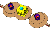
Schematic illustration of the FIRI spacecraft. (Credit:ESA) |
Initially two concepts were identified as the most promising candidates for FIRI: a formation flying concept and a concept using a single spacecraft with a central hub and telescopes located on a boom.
The formation flying scenario would be able to provide very large baselines and thus a high spatial resolution. However this concept is already under investigation for the Darwin mission and would have as a disadvantage the complexity and expensiveness of developing and operating multiple spacecraft.
The disadvantage of the boom scenario is the limit in the baseline that can be achieved and thus the spatial resolution is lower than with formation flying. The cost of the boom concept, however, is likely to be lower than formation flying and the boom technology is of general interest for establishing new generic technologies to be used in future missions. All considered the single spacecraft concept was selected by ESA as the baseline for the FIRI TRS. To obtain the required angular resolution a baseline of 30 m is needed and the telescope booms therefore need to be deployed after launch.
| FIRI mission summary | ||
| Mission | Launcher | Ariane 5, ECA |
| Orbit | L2 | |
| Lifetime | 5 years | |
| Interferometer | Michelson | |
| Baseline | 30 m | |
| Payload Module | Mass (dry) | 2590 kg |
| Telescope | Ø ~ 1 m | |
| Detector | 4 × TES(*) | |
| Detector temperature | 50 mK | |
| Optics temperature | 5 K | |
| Service Module | Mass (dry) | 2180 kg |
| Power | 2200 W | |
| Propellant | 420 kg | |
| AOCS | Reaction Wheels | |
| Communication | Ka-band | |
| (*) Transition Edge Sensors |
Orbit
A halo orbit around L2 with a semi-major axis of about 800 000 km was selected, which has the following advantages:
- simpler thermal design and minimizing perturbations
- direct insertion into operational orbit is possible
- limited need for orbit maintenance manoeuvres: only a few times per year, greatly reducing the amount of propellant needed
Science Operations
In order to make a proper image, an interferometer needs to sample the uv-plane. This can be achieved by moving the telescopes to different positions to create different baselines in different directions. For FIRI this is done by rotating the spacecraft while the mirrors are moving radially along the deployed booms. FIRI is designed to allow a range of different observing strategies, depending on the type of observation.
Spacecraft
The FIRI spacecraft consists of two main elements: the payload module (PLM) and the service module (SVM). The PLM contains all the optical elements, the detector and the cooling system. The SVM contains the spacecraft subsystems, including the translation mechanism of the telescopes.
Thermal
The cryogenic systems are large resource drivers for the FIRI mission as they need to cool the mirrors as well as ensure the very low temperature (50 mK) of the detector. Three independent systems are required, one on each telescope and one in the hub with a different design to accommodate the detector and the heat dissipation coming from the mechanisms housed in the hub. Both designs use a combination of passive cooling, sunshields and active cooling to reach the low temperatures of 5 K for the telescope optics (and 50 mK for the detector in the hub).
Mechanisms
The main mechanism of FIRI is the one responsible for the translation of the telescopes. A simple design was chosen as the baseline by minimising complexity and cost rather than mass. The mechanism can be divided in two parts: a drive unit and a guide unit. The drive unit is based on a pinion and rack design and uses mostly ‘off the shelf' components. The guide unit is based on a design solution used for the MIPAS instrument onboard Envisat (see related link on the right-hand side). The mechanism movement range, known as the stroke, however will need to be increased from 40 cm to 14 m.
Data Handling
A total mass memory of 1.3 Tbit including margin and redundancy is needed. This accommodates the science data and the large amount of data created by the metrology.
Telemetry, Tracking and Command
The current baseline is to have a system compatible with almost 50 Mbps max data rate. A Ka-band TT&C system is envisaged to allow for the high data rate necessary to download all data created by collecting two images in a single ground contact of about two hours.
Attitude and Orbit Control System
For pointing of the spacecraft, a regular system of four reaction wheels mounted as a tetrahedron will be used. As the two telescopes are moved along the booms, compensatory manoeuvres need to be made to maintain a constant spacecraft spin rate. These manoeuvres will be performed by a system of reaction wheels.
Power
Three independent power systems are used, one on each telescope and one on the hub, to avoid having to route power over the large boom distances.
Payload Definition
Interferometer
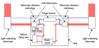
The interferometer comprises three main elements
- two light collecting telescopes on a boom
- two hub telescopes, located in the central hub
- beam mixer, also located in the hub
 |
|
Basic optical layout of the interferometer. (Credit: ESA) |
Telescope Design
The two telescopes on the boom are identical on-axis telescopes, consisting of two aspheric reflectors, a parabolic reflector and a folding mirror. The primary mirrors have a diameter of ~1 metre. The telescopes have an overall magnification of 5, resulting in a collimated beam diameter of ~20 cm being transmitted to the hub.
The two telescopes have strict positioning and pointing requirements with respect to both each other and the hub. The positions of the telescopes need to be stable during measurements and the exact pointing of the two telescopes needs to be known as well as the relative pointing between them to ensure coherent overlapping of the two collimated beams in the beam combiner. This precise alignment will be provided by tip-tilt mirrors and other mechanisms in the optical train.
Hub Telescopes
The central hub houses two identical off-axis light collecting telescopes with a magnification of about 5, resulting in an overall magnification before the delay line of ± 25. The hub telescopes are slightly oversized with respect to the incoming beam diameter in order to compensate for any deflection of the booms.
Beam Mixer
The beam mixer is designed for a Michelson interferometer. The recombination of the beams is based on using double-Fourier spatio-spectral interferometry, which has already been demonstrated for shorter wavelengths. Using this method over FIRI's large band (25-300 μm) would require a very long stroke of the order of 300 mm for the optical delay line. Additional issues with the required large band width are:
- It is harder to meet spectral resolution requirements over the entire band
- A large band width implies that the coherence length would only represent a small fraction of the primary beam
For these reasons FIRI's spectral band is split up into four sub-bands, each covering approximately 1 octave. This allows the optical stroke to be reduced to ± 70mm, or a mechanical stroke of ± 35mm.
| Characteristics of the FIRI spectral bands | |||
| Band # | λmin | λmax | # of pixels |
| 1 | 25.0 | 46.5 | 18 × 18 |
| 2 | 46.5 | 86.6 | 10 × 10 |
| 3 | 86.6 | 161.2 | 6 × 6 |
| 4 | 161.2 | 300.0 | 4 × 4 |
Fringe tracking is done by observing interference of the light coming from objects in the 3 arcminute field of view of a dedicated fringe tracking detector (a the science targets might be too faint for this purpose).
Metrology
This system is needed to measure the internal optical path difference between the optical trains of the two telescopes. It uses an internal laser to measure the distances to the collector telescopes located on the beams. An absolute metrology system is used to estimate the position of the telescopes with respect to the hub. Such a system would be based on developments carried out in the frame of the Darwin mission.
Detector
The detector will be comprised of four different detectors, one for each wavelength band and each with a different number of pixels and pixel sizes. Currently there exists no detector in array format with the required performance of a noise equivalent power in the order of 10-20 W/Hz½.
One promising detector technology for achieving this sensitivity is Transition Edge Sensors (TES). The size of a typical TES is small, which would lead to a large number of pixels required to fill an array. To reduce this number a lens matched to the wavelength of interest would be located in front of the TES. This facilitates an easier match between the size of the TES and the telescope optics in addition to increasing the efficiency of the detector.
The TES operates at about 50 mK, which is a major design driver for the cooling system. To avoid different focusing for each detector it is envisioned that all the detectors have the same overall dimensions.
Challenges
To enable a mission as complex as FIRI substantial technology development effort is required, specifically in the field of cooling, optics and detector technology.
Study Details
The current FIRI study has shown that the selected mission concept is quite ambitious and is feasible only with significant technology development. Nevertheless, the baseline selected for FIRI is a promising one as it is less complex than a far infrared mission involving formation flying.
This study was completed in 2006. It was performed by SRE-PAM in cooperation with the Concurrent Design Facility, CDF.
Contact
Nicola Rando
Head of Science Missions section (SRE-PAM)
Advanced Studies and Technology Preparation Division
ESA - ESTEC, Keplerlaan 1, 2201 AZ Noordwijk, The Netherlands
Nicola.Rando esa.int

