No. 25 - SMART-1 Observes the Earth
The Electric Propulsion power has been increased from 1311 W to 1361 W, as the power margins on the spacecraft are comfortable and operating at higher power saves some fuel. We are now very close to the minimum power (early July) due to the farthest distance from the Sun.
The thruster change of state, caused by the varying amplitude of the anode current oscillation (see status reports #23 and 24) with consequent slight variation of thrust are still observed. The experts continue their investigation. No Optocoupler Single Event Transients, causing the flame-out, have been observed during this period.
Up to 20 June, the ion-engine had cumulated a total ON time of about 2535 hr, consumed about 40 kg of Xenon (48% of the total propellant on board) and imparted to the spacecraft a velocity increment of about 1850 ms-1.
Science Update
The cruise phase planning has been consolidated until the November 2004 lunar capture.
 |
|
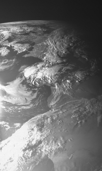
AMIE picture of Europe and Africa |
AMIE
The camera has obtained an image of Europe through the black and white clear channel, from an altitude of 70 000 km. This opens a series of synoptic images of the Earth during the cruise phase that will be used for calibration, validation of Moon imaging mode, as well as providing terrestrial scenes for comparison, and exciting views of our home planet.
D-CIXS and XSM
The D-CIXS X-ray spectrometer is continuing to measure bright X-ray sources during the coast arcs, and the X-ray Solar Monitor (XSM) is monitoring the Sun as an X-ray star.
STWT
The Science and Technology working team at its last meeting, has confirmed agreement for a lunar orbit with an apolune around 3000 km and a period of 4.96 hours. This will allow a good coverage up to 50 degrees North with less than 800 km distance, providing high resolution conditions for the AMIE and SIR instruments, and overall higher sensitivity for the D-CIXS X-ray spectrometer. The lunar science planning is being optimized with the new lunar orbit, illumination, and operational constraints.
Latest results from SMART-1 and its instruments can be found under presentations posted in the left navigation on these SMART-1 pages. Various papers based on early SMART-1 results will be given at the Asian Oceanian Geophysical Society meeting in Singapore (6-8 July), and at COSPAR at Paris during the lunar session on 22-23 July.
How the semi-major axis changes
The attentive reader will have noticed that the rate of change of the semi-major axis (and of all other orbital elements related to it, like the period and the distances from Earth) is much higher now than earlier in the mission. This is despite the fact we use always the same engine, with roughly the same thrust (in reality even with a slightly lower thrust as explained above) and for roughly a third of the time, as before. Why do we see now these large 'jumps' and why is the orbit expansion progressing much faster than before?
According to the orbital mechanics as established by Newton and further developed by Joseph Louis Lagrange (after which the Lagrangian points are named), the rate of change of the semi-major axis a, for a given acceleration imparted by an engine, is given by the formula:

Hence the rate of change is proportional to the square root of the semi-major axis to the third power divided by the factor (1- eccentricity squared). Over the course of the mission the eccentricity of the orbit has changed from its original value of 0.71 at GTO, to a minimum of 0.48 and is now increasing again to a current value of 0.68. The semi-major axis instead has constantly increased as reported regularly. If you take the formula above and put in some numbers, you will see that the rate of change of the semi-major axis is now six times larger than at the beginning of the mission and it will continue to grow as long as the semi-major axis and, to a lesser extent, the eccentricity grow.
This effect can be more easily understood by considering the reduction in the gravitational force acting between the Earth and the spacecraft. The force, which decreases by the distance squared, is now considerably weaker than in the initial orbit. As a consequence the spacecraft's engine now has to do less work to overcome gravity, or put another way has more power available to escape from the Earth.
Orbital/Trajectory information
The osculating orbital elements are periodically computed by the ESOC specialists. These elements define the osculating orbit which would be travelled by the spacecraft if at that instant all perturbations, including EP thrust, would cease. So it is an image of the situation at that epoch. In reality the path travelled by the spacecraft is a continuous spiral leading from one orbit to another. The most recent osculating elements are as follows:
|
EPOCH (UTC) 2004/06/26 21:31:22.7 Elements WRT Earth (J2000) |
|
| Pericentre Distance (km) |
27 408.087687 |
| Apocentre Distance (km) |
142 481.058975 |
| Semi Major Axis (km) |
84 944.573331 |
| Eccentricity |
0.677342 |
| Inclination (deg) |
6.811121 |
| Asc. Node (deg) |
135.227620 |
| Arg. of Pericentre (deg) |
220.136826 |
| True Anomaly (deg) |
180.054406 |
| Osc. Orbital Period (h) |
68.440306 |
|
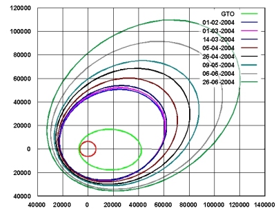
SMART-1 osculating orbit up to 26 June 2004 |
In this diagram the osculating orbits at launch (GTO) and at different times are plotted. The large effects that the operations of the electric propulsion now have on the orbit expansion is clearly visible. Especially the height of the apogee has dramatically increased and now exceeds one third of the Earth Moon distance. Since the start of the mission, the electric propulsion system has changed the orbital parameters as follows:
- The semi-major axis from 24 626 km to 84 944 km
- The perigee altitude from 656 km to 21 030 km
- The apogee altitude from 35 880 km to 136 103 km
- The orbital period from 10 hours 41 minutes to almost 3 days
Contact Points
Giuseppe Racca
SMART-1 Project Manager
ESA/ESTEC - SCI-PD
Keplerlaan 1- 2200 AG Noordwijk, The Netherlands
E-mail: Giuseppe.Racca esa.int
Bernard H. Foing
SMART-1 Project Scientist
ESA/ESTEC - SCI-SR
Keplerlaan 1- 2200 AG Noordwijk, The Netherlands
E-mail: Bernard.Foing esa.int


