Deployable sunshield
The sunshield's large diameter is driven by the fact that the Gaia spacecraft maintains an angle of 45° between its central axis and the anti-Sun direction. To fit inside the launcher fairing the sunshield will be folded against the sides of the spacecraft during launch, forming a cylinder around the spacecraft. It will deploy after the spacecraft has separated from the launcher, opening 90 degrees to form a disk.
| Quick facts of sunshield | |
| Diameter | 10.2 metres when fully deployed |
| Framework | 12 rectangular rigid frames (0.8m × 3.2m). Made of CFRP tubes joined by metallic fittings. Frames are hinged at the base, for deployment. |
| Thermal shields | 2 parallel MLI blankets, each comprising: - 12 fixed rectangular sections, and - 12 foldable triangular sections |
| Solar flux is reduced by a factor of 280 | |
| Planarity | Sun-side blanket kept flat within 10mm throughout mission |
| Solar panels | 8 solar array panels installed on 8 of the 12 frames |
Structure and composition
The structural framework for the deployable sunshield is formed by 12 H-shaped rigid frames, made of carbon-fibre reinforced plastic (CFRP) tubes that are joined by metallic fittings. This framework supports two parallel blankets of multi-layer insulation (MLI) that act as the thermal shields. The blanket on the Sun-side of the framework is made of 2-layer MLI and the one on the shadow-side is a 5-layer MLI.
The two parallel MLI blankets both consist of fixed rectangular sections that cover the 12 frames, plus foldable triangular sections that cover the space between the frames. The foldable sections are rolled up when the sunshield is stowed for launch, and unroll during deployment. Together the fixed and foldable sections form the complete sunshield.
 |
 |
|
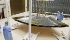
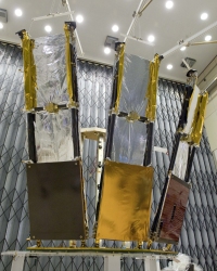
Two views of the sunshield, semi-deployed, during testing of a qualification model in July 2009. Left: the Sun-side MLI is not yet fully installed so the H-shaped CFRP frames are visible (only three frames make up this qualification model). The outer two frames are equipped with the base plate for a solar panel. Right: all MLI is in place, including the foldable triangular sections between the frames. Credit: ESA. |
|
For the shadow-side blanket, the part covering each frame is made up of a single section of MLI. For the Sun-side blanket the MLI over each frame is made up of a lower part and an upper part. Eight of the 12 frames of the deployable sunshield will be equipped with a solar panel. These frames will only have the upper part of the Sun-side MLI, with the lower part of the frame covered by a different type of MLI for insulation underneath the solar panel.
All the rectangular sections and the triangular sections of the sunshield MLI are attached to the frames through tensioning devices, which hold the sections at their corners and keep the two parallel blankets of the sunshield in place.
Deployment of the sunshield
 |
|
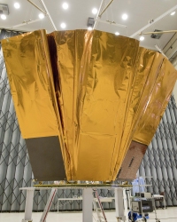
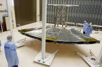
The qualification model of the sunshield, made of three frames and with the two parallel MLI blankets in place, seen in fully deployed configuration. |
The controlled deployment of the sunshield is initiated by the firing of small pyrotechnics in the release nut fitting on each frame, resulting in the release of the separation bolt (which is then retracted and retained into the fitting on the thermal tent) and thereby the release of the frames.
All frames have two hinges at their base, with one at each corner of the frame. Each hinge has two loaded springs that provide a force in the deployment direction. It is these springs that drive the sunshield's deployment.
The hinges of adjacent frames are connected by a flexible metal coupling that spans the 30° angle between two frames. Together the 12 flexible couplings ensure a synchronous deployment of the sunshield frames.
After release of the 12 frames from the spacecraft sides the deployment is controlled by a regulator installed on what is called the master frame. The regulator is connected to one of the master frame's hinges. It is a cylinder filled with an alloy that has a low melting point. Initially the alloy is solid and prevents the part inside the cylinder that is attached to the hinge from moving, thereby keeping the sunshield from deploying. By heating, the solid alloy melts and the resistance against deployment is reduced. This allows for a controlled and smooth deployment.
When the sunshield is fully deployed, the regulator is switched off so that the alloy is left to cool again and solidify. Together with the hinge springs this will keep the sunshield steadily in its deployed configuration throughout the mission.